
HandiQuilter.com
Page 11
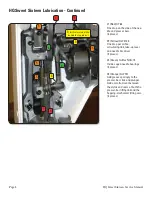
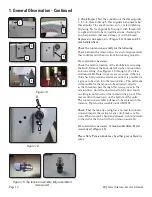
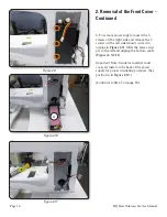
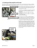
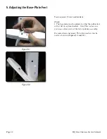
Loosen the set screw under the top tension assembly
a couple turns as it fi xed into an undercut into the top
tension base. (Screw A,
Figure 1.4
on previous page.)
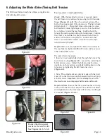
Note that the set screw is on about a 30° angle to the
machine front cover. Loosen the slotted set screw at
the rear of the top tension base and rotate the split bolt
until the spring returns to the end of the slotted groove
when pushed and released. Re-tighten the set screw
fi rmly.
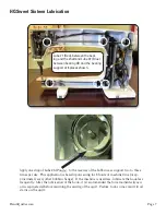
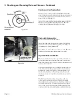
If the take-up spring needs replacing, remove the ten-
sion parts and split bolt and carefully work the spring
around until it can be removed. Replace with a new
take-up spring (Part #QM10197). Make sure the split
bolt is inserted all the way into the base and retighten
the slotted screw. Adjust the take-up spring tension so
that it barely returns to the end of its slot when pressed
to the side and released.
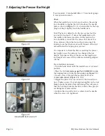
Figure 1.8
shows this position.
NOTE: Too much spring tension will affect the stitch
quality.
Reinstall the top tension parts on the split bolt and then
the assembly into the machine front cover and tighten
the set screw.
Radial postion: When the top tension assembly is prop-
erly installed into the machine front cover, the straight
part of the take-up spring (before the loop) will be
straight up at 12 o’clock (or a little bit towards
11 o’clock). (
Figure 1.4, Position B on previous page.
)
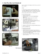
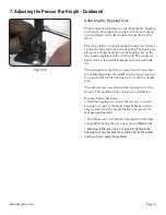
Check that the top tension knob is not too loose
on the
split bolt and that it has some resistance so that it will
not vibrate loose while sewing.
If a correction is necessary:
To correct: remove the knob, detent washer and cone
spring, adjust the split bolt by spreading with a fl at
screwdriver until the knob has adequate resistance to
keep its setting.
Caution:
The split bolt is hardened and if adjusted too
much it may break. The top tension assembly will
then needs to be replaced. (Top Tension Assembly Part
#QM10198)
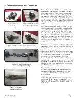
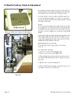
Figure 1.6. Knob
removed
Figure 1.7 Detent washer
and cone spring removed
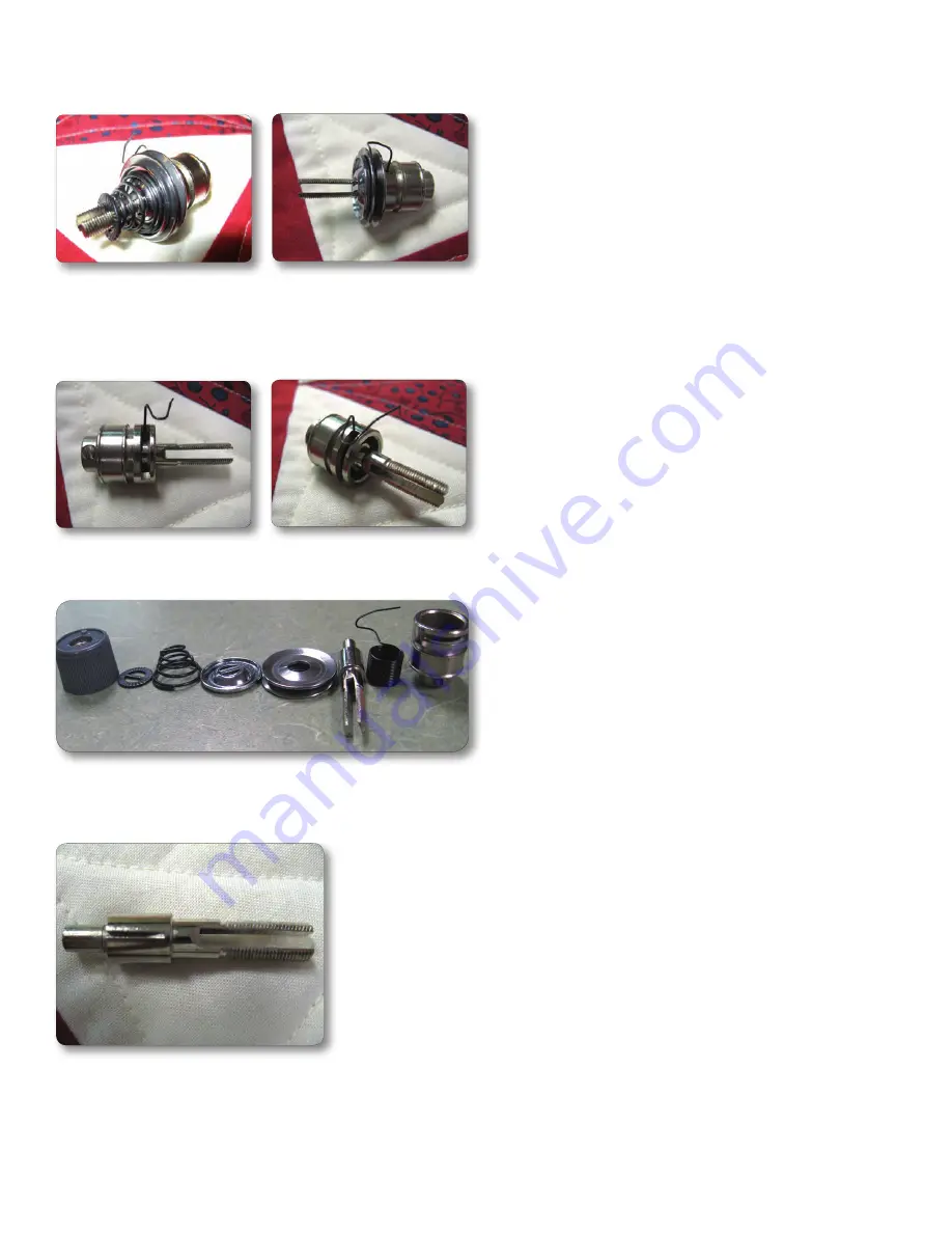
Figure 1.8 .Tension discs removed (two views)
Figure 1.9. Fully disassembled,
laid out in order of assembly
Figure 1.10. Tension
assembly split bolt
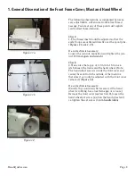
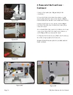
1. General Observation - Continued
1. General Observation - Continued


