background image

7 b.  .  Adjusting the Presser Bar Height  

Version B (Newer Machines) 

(Tools required:  3 mm handle allen,  0. 5mm feeler gauge) 


Check: 

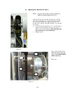
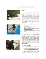
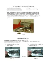
Figure 13.1 


When the needle bar is in its lowest position, the 
sewing foot should be no higher than 0.5mm above the 
needle plate as shown in Figure 7.3.  It is permissible 
for the sewing foot ring to lightly touch the needle plate.  

Note:  the factory default on the sewing foot:  screwed 
into the presser bar 7 revolutions.  To check the foot, 
without removing it, there should be about 13-15 
threads of the foot exposed below the hopping foot jam 
nut.

  It is important to check this before resetting the 

presser bar height in case the end user has changed the 
foot height.  Improper setting of the presser bar height 
and foot height can cause stitch problems including 
skipped stitches. 

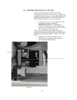
Figure 7.3


     If a correction is necessary:


Turn the handwheel until the needle bar is at its 
lowest position.   


Place the (

0.5mm feeler gauge)

 under the 

hopping foot.  Figure 7.3 


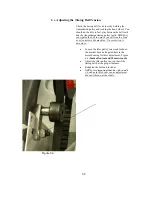
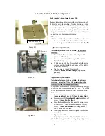
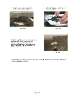
Loosen screw C through the machine front cover  

(3mm allen driver) 

Figure 7.4 


Wiggle the presser bar up or down to the desired 
position. 


Tighten screws C. Figure 7.4 – push down lightly 
on the tool blade towards table while tightening. 


7 c.  Adjusting the Presser Foot (Sewing Foot) 


The HQ-Sixteen features the “

KinetiQuilt”

 hopping 

mechanism, allowing the sewing foot to move (hop) up, 
down, and dwell on the fabric when the needle is in the 
fabric. This allows fabric to move through the machine 
similar to a normal sewing machine with a feed dog. 
The dwell time allows for a longer hesitation of the foot 
on the fabric and completion of the stitch cycle.  The 
results are better tension, less needle breakage, and 
increased hook life. 
 

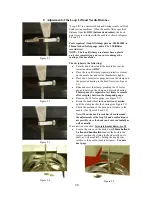
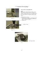
If a correction is necessary: 


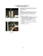
Install the loop lift clamp onto the right angle bend of 

the sewing foot as shown in Figure 7.5. While 
holding the clamp and foot, loosen the jam nut. 
Screw the foot shaft to the desired height.  Tighten 
the jam nut.  

(clamp, 8mm open end wrench)


Note: Under NO circumstance loosen or tighten the jam 
nut without HOLDING the sewing foot as indicated.


Figure 7.4 

Figure 7.5 

7.1 

Содержание HQ Sweet Sixteen

Страница 1: ...Service and Troubleshooting Manual 12 20 06 Handi Quilter LLC...

Страница 2: ...ay Check and Adjustment 4 Adjusting the Base Plate 5 Adjusting the Motor Belt Tension 6 0 Adjusting Transmission Gear Lash play 6 1 Adjusting the Timing Belt Tension 6 2 Adjusting the Presser Bar Heig...

Страница 3: ...nd explanations that we hope will aid you in your repair efforts Additional to the teaching aids found herein you will also find all of the tools listed that are necessary for adjustments If you need...

Страница 4: ...ation of hook Velocite 10 Texaco 22 Assembly Torque Specifications The Torque Specifications apply to all internal fasteners in sizes 4 0 5 0 and 6 0mm in general at ISO 4762 Screw class 8 8 The torqu...

Страница 5: ...OY Main bearing reservoirs 3 Kluber GLY 2100 Take up articulating link 4 Kluber NCA 15 Isoflex Take up caged Needle bearings 5 Kluber GLY 151 Polylub Transmission gears 6 Conoco Hydroclear R O 32 Hoo...

Страница 6: ...r gel Lube 2 Blue on the side of the bearing and or under the bearing retainer straps Kluber Constant OY 68 1 Red and Mikrozella G8 0Y 2 Blue Lube 3 Yellow Kluber GLY 2100 the take up and articulating...

Страница 7: ...machine time If the machine is used less lubricate the hook less frequently After the lubrication of the hook it is recommended that one momentarily sew on scrap material before resuming the sewing of...

Страница 8: ...e and presser bars One drop in the needle bar driver orifice 5 Orange GLY 151 Add grease sparingly to the presser bar slide Add a small amount on between the stylus and cams of both the presser bar li...

Страница 9: ...2 Blue Mikrozella G8 0Y Add a dab to the end of each bearing bushing 1 Red OY 68 One drop on each bearing bushing 5 Orange GLY 151 Add a small dab to reduce gear noise 0 4...

Страница 10: ...ry Loosen the jam nut reposition and tighten the jam nut 2 Make sure that a gap of 1 0mm to 1 5mm exists between the frame and the hand wheel Note This can only be adjusted when the front frame cover...

Страница 11: ...prevent the disks from functioning properly If a correction is necessary remove the knob tick washer tension disks and core spring Clear and reassemble Check that the take up spring has a normal torsi...

Страница 12: ...ess to the frame screw then re snug 2mm handle allen tool A Figure 2 1 2 Remove the three frame screws as shown in Figure 2 2 3mm handle allen tool Figure 2 2 3 Remove the C pod by unscrewing the 4 sc...

Страница 13: ...behind the C print removed in step 4 4mm handle allen may need 4mm L allen tool to break loose screws 7 Separate the Front Frame Cover Make sure the take up lever does not get caught in the frame slot...

Страница 14: ...The C Pod and the P Pod are STATIC SENSITIVE parts and should not be handled without special discharge tools For this reason all C and P Prints will be exchanged in the pod covers Do not remove the P...

Страница 15: ...thus securing and assuring that timing will not change see figure 3 1 Note See torque specifications chart in the specification section for torque values Figure 3 1 Thrust Collar NOTE The thrust coll...

Страница 16: ...igure 3 5 Hand wheel Secondary Drive Pulley Drive pulley screws 2 5mm handle allen Figure 3 7 Hookshaft gear screws 2 5mm handle allen Figure 3 6 Transmission gear and pulley screws 2 5mm handle allen...

Страница 17: ...2 Check the transmission shaft by pushing and pulling axially on the gear as shown in Figure 4 3 If a correction is necessary Loosen the second screw on the gear first and use the first screw screw on...

Страница 18: ...is necessary 0 012 shim washers may be used as shown in Figures 5 1 and 5 2 Figure 5 1 Figure 5 2 Adjustment of Base Plate Rollers The base plate rollers must be equally spaced in their respective pos...

Страница 19: ...finger pressure but should not be so tight as to bind the machine If a correction is necessary Loosen the motor frame screws 1 2 3 and 4 shown in Figure 6 2 and slide the motor frame up or down to ac...

Страница 20: ...elongated slots on the transmission housing above the gear 4mm allen tool figure 6 3 see left arrows Adjust the transmission mount with elongated slots up for more lash and down for less lash until i...

Страница 21: ...will create a bind or extra noise in the machine If a correction is necessary Loosen the idler pulley screw and locknut the bracket has an elongated hole in the motor housing for idler adjustment Figu...

Страница 22: ...bar must be 1 5 above the needle plate as shown in Figure 7 1 If a correction is necessary Remove the sewing foot NOTE make sure to hold the foot while loosening to prevent presser bar damage from th...

Страница 23: ...he hopping foot Figure 7 3 Loosen screw C through the machine front cover 3mm allen driver Figure 7 4 Wiggle the presser bar up or down to the desired position Tighten screws C Figure 7 4 push down li...

Страница 24: ...e head frame back into the main casting gently slide the head frame left or right to correct as necessary Tighten screws A and B in figure 8 2 Note If needle position changes repeat the process Adjust...

Страница 25: ...bearing in the head frame see Figure 9 1 Raise and reset the clamp pinching the 2 2 feeler gauge in between the clamp and projected bearing This step may be repeated a few times to remove all excess p...

Страница 26: ...led from below figure 9 6 Figure 9 6 Figure 9 7 Stop finger engaged without bobbincase from above figure 9 7 Rotate the basket out of the way to facilitate the needle distance adjustment Important aft...

Страница 27: ...screw driver through the access hole See figure 10 2 Loosen the screw slightly so that the needle bar can be wiggled up or down to the correct position Note Under NO circumstance should the needle ba...

Страница 28: ...earance of 0 8mm to 1 0mm This clearance ensures that adequate space exists for thread escapement during the sewing process If an adjustment is necessary Loosen screw A in Figure 11 1 and adjust the s...

Страница 29: ...Loop Lift Clamp and 2 2mm feeler gage as shown in the Adjustment of Loop Lift and Needle Distance Section check loop lift If the machine requires a Loop Lift adjustment remove the stop finger and hook...

Страница 30: ...ugh the needle eye and compare the upper and lower levels of the eye with the Cylinder tool groove If an adjustment is necessary loosen the needle bar driving clamp slightly and raise or lower the nee...

Отзывы: