


HAMWORTHY HEATING LTD. PUREWELL PERMANENT IGNITION 500001090/B
5
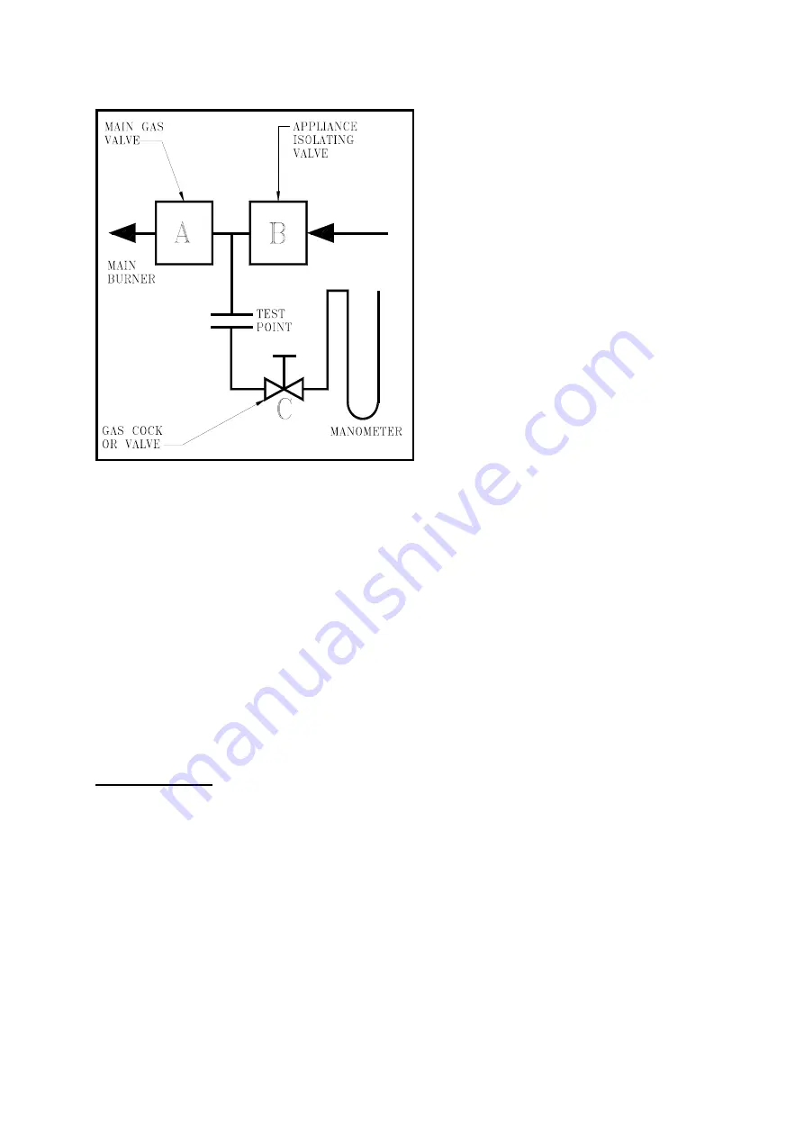
3) With A, B closed open C and monitor manometer
over a 2 minute period, a rise indicates a leak on
valve B.
Figure No. 3 Gas Valve Leak Check Procedure
Note: -
Main Gas Supply Pressure:
G20 - 20mbar
G31 - 37mbar
TO CHECK VALVE A
1) Open C.
2) Open B to produce the main gas supply pressure
between A and B.
3) Close B
4) System may be considered sound if over a period
of 2 minutes any drop in pressure is less than
0.5mbar (0.2" wg.).
NOTE:
Allow a manometer stabilisation period of
approximately 1 minute before each 2 minute check
period. Following soundness tests close valve B and
remove manometer connections and tighten test
points.
6.0 FLUE SYSTEM
Detailed recommendations for flue systems are
given in
BS 6644,
I. Gas E. Publication,
IGE/UP/10
"Installation of gas appliances in industrial and
commercial premises Pt.1 flued appliances".
The following notes are intended to give general
guidance only.
6.1 General Requirements
The Hamworthy Purewell Series of boilers are
designed to be used with natural draught flues. Flue
systems should be designed in accordance with
current regulations and with reference to the I. Gas
E. publication
IGE/UP/10
"Installation of gas
appliances in industrial and commercial premises
Pt.1 flued appliances". The following points should
be noted: -
1)‘Classic’
boilers
MUST
have the correct draught
diverter and primary flue duct, or optional primary
flue damper, fitted in an unmodified condition before
connection to the flue system.
‘Integra’
boilers
MUST
have the flue hood
incorporating the draught diverter, fitted in an
unmodified condition before connection to the flue
system.
2)
The bottom of the flue header should be at least
500 mm above the draught diverter skirt bottom.
3)
The flue system must be self-supporting in the
correct position to avoid compression of the draught
diverter and enable its removal for boiler cleaning.
4)
Boilers should be located as near the chimney as
possible the nearest being not more than 2m (6 ft)
away.
5)
The flue system should be designed to achieve a
negative suction at all times at the draught diverter
outlet on all modules in a bank. For optimum
performance, draught conditions should be between
-0.05 to -0.125mbar. In the case of a single boiler
installation, the minimum vertical flue height is 2m
above the draught diverter skirt. For multiple boiler
installations consult Hamworthy Heating Technical
Department. In some instances, mechanical
assistance may be necessary. The boilers are
suitable for connection to a fan diluted flue system,
refer to I. Gas E. publication
IGE/UP/10
"Installation
of gas appliances in industrial and commercial
premises Pt.1 flued appliances".
6)
Purewell boilers are suitable for installation in a
balanced compartment in accordance with the
requirements of
BS 6644
. Consult Hamworthy
Heating Technical department for help or assistance
if in doubt.
6.2 Design Waste Gas Volume and Temperature
It is recommended that the volume and temperature
of the waste gases used for design of the flue
system be as shown in Figure No. 1 for Natural Gas.
Information relating to propane firing can be found in
Appendix ‘A’.
6.3 Flue Condensation
Care should be taken to ensure that the flue is
installed in such a way that any condensation
produced on start up will drain away naturally.
6.4 Materials
Materials used for the flue system must be
mechanically robust, resistant to internal and
external corrosion, non-combustible and durable
under the conditions to which they are likely to be
subjected.
6.5 Disconnection
On
‘Classic’
models, the draught diverter is
designed to enable separation from the primary flue
duct, or optional damper, such that it can be lifted
clear of the boiler to ease disconnection. The flue
must be correctly reconnected when servicing is


