background image

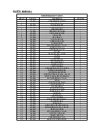
PARTS MANUAL 

FULL SHIFTING ASSY.

REF NO.

PART NO.

DESCRIPTION

REQ’D NO.

1

9.110.020

BOLT-WASHER M10x20

2

2

9.110.100

BOLT-WASHER M10 x 100

3

3

6.000.240

GEAR BOX SUSPENSION ARM

1

4

8.010.168

COLLAR #1

1

5

9.112.230

BOLT-WASHER M12x1.25x230

1

6

6.000.239

PIVOT ARM SHIFT C

1

7

7.020.068

CUSHION BUSH

4

8

9.220.012

LOCKING FLANGE NUT M12

2

9

8.010.167

COLLAR #2

1

10

9.112.190

BOLT-WASHER M12 x 1.25 x 190

1

11

6.000.238

PIVOT ARM SHIFT B

1

12

9.110.200

BOLT-WASHER M10 x 1.25 x 200

1

13

9.220.010

LOOKING FLANGE NUT M10

5

14

6.000.237

PIVOT ARM SHIFT A

1

15

7.010.004

PEDAL BUSH

2

16

9.108.145

BOLT M8x1.25x145

1

17

6.000.235

RIGHT TURN CLEVIS ROD HEAD

1

18

9.110.030

BOLT-WASHER M10x30

2

19

9.200.010

RIGHT TURN NUT M10

1

20

6.000.236

SHORT CLEVIS ROD

1

21

9.200.010-L

LEFT TURN NUT M10

1

22

6.000.234

LEFT TURN CLEVIS ROD HEAD

1

23

9.110.040

BOLT-WASHER M10x40

1

24

6.000.233

LONG CLEVIS ROD

1

25

9.700.513

PIN 

Φ

5x13.5

1

26

9.500.212

COTTER PIN

1

27

4.000.031

SHIFTER HOUSE ASSY.

1

28

9.100.612

BOLT M6 x 12

4

29

6.000.258

PARKING BRAKE ASSY.

1

30

9.108.020

BOLT-WASHER M8 x 20

2

31

9.300.008

WASHER 

Φ

8

2

Содержание UM250IIR 2005

Страница 1: ......

Страница 2: ......

Страница 3: ...IGHT SIDE COVER ASSY Fig 5 6 CRANKSHAFT CON ROD PISTON ASSY Fig 6 7 VALVE TRANNYASSY 1 Fig 7 8 VALVE TRANNY ASSY 2 Fig 8 9 LEFT SIDE COVER ASSY Fig 9 10 WATER PUMP ASSY Fig 10 11 CARBURETOR COMP Fig 1...

Страница 4: ...Be sure to follow the recommended maintenance schedule and service your kart accordingly Preventive maintenance is extremely important to the longevity of your kart Beginners should seek instruction...

Страница 5: ...kart You must use your own good judgment You will find important safety information in a variety of forms including Safety Labels On the kart Safety Messages Preceeded by a safety alert symbol and on...

Страница 6: ...ves and other protective gear Drive Off Road Only Your kart is designed and manufactured for off road use only The tires are not made for use on pavements and the kart does not have turn signals and o...

Страница 7: ...n the dark vision can greatly reduce a driver s visibility and judgment So driving at night is dangerous and can increase the possibility for an accident Never run your kart indoors The exhaust from t...

Страница 8: ...ant information and recommendations to help you drive your kart safely Please take a few moments to read these pages The labels should be considered permanent parts of the kart If a label comes off or...

Страница 9: ...e clothing You don t have any alcohol or drugs in your system ARE YOU READY TO DRIVE Protective Clothing For your safety we strongly recommend that you always wear an D O T approved motorcycle helmet...

Страница 10: ...size and weight IS YOUR VEHICLE READY TO DRIVE Before each drive it is important to inspect your kart and make sure any problems you find are corrected A pre drive inspection is a must not only for s...

Страница 11: ...and control the kart When driving off road also remember to always obey local off road driving laws and regulations Obtain permission to drive on private property Avoid posted areas and obey no trespa...

Страница 12: ...errain Radiator Indicator Lamp During the driving you should always keep close contact with this red indicator lamp This indicator lamp will tell you when your engine coolant system is getting too hot...

Страница 13: ...8 9 foot lbs e Install Front Tires and tighten the nuts f Install Rear Tires tighten the nuts insert cotter Pin and put on the Rubber Cover g Raise the C B C bar as the picture shows h Install C B C b...

Страница 14: ...rrected compression ratio 10 1 Carburetor VEKS4 CV30 Output Power 10 5Kw 7000rpm Maximum Torque 17 6N m 5500rpm Starting Electric Ignition C D I Lubrication Force Splash Transmission Automatic C V T s...

Страница 15: ...ot control Front tire 20 x 7 8 Rear tire 22 x 10 10 Front Suspension Independent Dual A Arm Rear Suspension Full Independent Rear Suspension Oil Damped Shocks Restraint System Dual 4 point Harness Fin...

Страница 16: ...rake The brake is the left foot pedal See Fig 1 Applying pressure to the pedal slows or stops the kart c Start engine Insert the key into key switch turn the key clockwise release the key when the eng...

Страница 17: ...ars are in place before operating the kart i Check the Lights Check the headlights brake light and tail light are all working j Check the Steering Check that the steering wheel moves freely in both di...

Страница 18: ...Operation Component locations Figure 2...

Страница 19: ...eat slide b Move the seat to the desired position c Be sure that the seat adjustment handle snaps back into place and that seat is locked into position Figure 3 E Forward and Reverse Gear a Push the b...

Страница 20: ...rollable speed when turning to prevent the kart from rolling over The driver should keep their heels on the ramp of the main board when turning See Fig 5 Keeping their leg on the foot pedal the driver...

Страница 21: ...rs of operation Add oil when necessary to keep the level between the bottom of the dipstick and the 0 mark Do not mix various grades of oil ENGINE OIL PLUG COVER Figure 7 C Spark Plug a Remove the spa...

Страница 22: ...h a clean rag wipe off all dirt and oil from around the controls Wipe off any spilled fuel and oil Keep the engine clean of foreign objects and be sure to check that the air intake fan is free of debr...

Страница 23: ...removing the spark plug and pouring a small amount of oil 1 2 Tbsp into the plug hole then re fit the plug c Do not save or store gasoline over winter Using old gasoline which has deteriorated from s...

Страница 24: ...re 13 next page a The front wheels should toe in from 1 8 to 1 4 inch To check for alignment measure distance A and B between the centerline CL of the wheels The proper toe in dimension A should be 1...

Страница 25: ...Figure 13...

Страница 26: ...ice Items Initial service first week Monthly Quarterly Yearly Tire pressure wear I I Brake performance I I Tightness of screws I I Air cleaner C R Carburetor I C Spark plug C A coolant Brake oil I I I...

Страница 27: ...WIRING DIAGRAM...

Страница 28: ...GE BOLT 1 5 152MI 023002 SPRING 1 6 152MI 023004 TENSIONER SEAL 1 7 172MM 023007 WATER INFLOW RUBBER TUBE 1 8 172MM 023009 WATER TUBE SHEATH 1 9 QC T621 1999 B24 WIRE CLAMP 2 10 152MI 023009 WASHER 8...

Страница 29: ...Fig 2 CYLINDER COVER ASSY 1...

Страница 30: ...I 021015 BOLT M12 x 1 25 1 13 152MI 021013 BOLT M8 x 25 1 14 152MI 021008 VISION HOLE CAP 1 15 152MI 021016 WASHER 8 3 16 152MI 021012 EAR WASHER 1 17 152MI 021014 WASHER 12 2 18 152MI 021009 VISION H...

Страница 31: ...Fig 3 CYLINDER COVER ASSY 2...

Страница 32: ...EMPERATURE RETAINER COVER 1 12 172MM 022400 SPARK PLUG 1 13 152MI 021017 FLANGE BOLT M6 x 25 2 14 172MM 022800 EX OUTLET SEAL 1 15 152MI 022600 WATER TEMPERATURE SENSOR 1 16 GB T6191 1986 INNER HEX FL...

Страница 33: ...Fig 4 CRANKCASE ASSY...

Страница 34: ...STUD BOLT B 1 13 172MM 011004 CYLINDER STUD BOLT A 3 14 NTN TMB301 ROLL BEARING 1 15 172MM 011007 BRAKE SHOE BUSH DOWEL PIN 1 16 172MM 011009 OIL SEAL 34 x 52 x 5 1 17 172MM 011001 OIL SEAL 28 x 40 x...

Страница 35: ...Fig 5 Right Side Cover Assy...

Страница 36: ...13001 DIPSTICK 1 12 172MM 013019 EXHAUST THREE JOINT 1 13 152MI 021008 VISION HOLE CAP 1 14 172MM 013031 FLANGE BOLT M6 x 80 1 15 172MM 013028 O RING 30 x 3 55 1 16 152MI 021009 VISION HOLE CAP SEAL 1...

Страница 37: ...N RING 1 172MM 040009 THE SECOND PISTON RING 1 2 172MM 042000 OIL RING ASSY 1 3 172MM 040005 PISTON 1 4 172MM 040007 PISTON PIN 1 5 152MI 040011 OIL TUBE JOINT 1 6 152MI 040010 OIL TUBE JOINT SPRING 1...

Страница 38: ...001 INLET VALVE 1 5 172MM 022005 EX VALVE 1 6 172MM 022002 OUTER VALVE SPRING 2 7 172MM 022003 INNER VALVE SPRING 2 8 152MI 022005 SPRING VALVE DISC 2 9 152MI 022001 SPRING VALVE SEAT 2 10 152MI 02200...

Страница 39: ...EF NO PART NO DESCRIPTION REQ D NO 1 172MM 022200 TIME CHAIN 1 2 172MM 023200 TENSIONER LOWER 1 3 172MM 023001 CHAIN GUIDE PLATE UPPER 1 4 GB96 85 6 D Zn BIG WASHER 1 5 GB T5781 2000 HEX FLANGE BOLT M...

Страница 40: ...FLANGE BOLT 2 5 152MI 012200 SHOCK ABSORPTION BLOCK ASSY 2 6 152MI 011007 DOWEL PIN 010 x 16 2 7 172MM 012008 OIL DISCHARGE BOLT VISION HOLE CAP 1 8 GBT818 2000 M5X8 CROSS FLANGE BOLT 4 9 172MM 01210...

Страница 41: ...4 172MM 080002 WATER PUMP HOUSING SEAL 1 5 172MM 080001 WATER PUMP SHAFT 1 6 152MI 013009 FLANGE BOLT M6 x 40 2 7 152MI 02017 FLANGE BOLT M6 x 25 2 8 GBT893 1 86 19 CIRCLIP 1 9 152MI 080007 WASHER 7 5...

Страница 42: ...PARTS MANUAL CARBURETOR COMP REF NO PART NO DESCRIPTION REQ D NO 1 172MM 100000 CARBURETOR COMP 1 Fig 11 CARBURETOR COMP...

Страница 43: ...IL PUMP SPROCKET 1 6 152MI 073000 OIL PUMP CHAIN 1 7 152MI 071004 INNER OIL PUMP ROTOR 1 8 152MI 071005 OUTER OIL PUMP ROTOR 1 9 152MI 070002 OIL PUMP DIVISION PLATE A 1 10 152MI 072000 OIL PUMP DIVIS...

Страница 44: ...VE BELT 1 8 172MM 052300 DRIVEN WHEEL 1 9 172MM 052100 MOVABLE DRIVEN WHEEL 1 10 172MM 052002 GUIDE COLUMN PIN 4 11 172MM 052001 GUIDE ROLLER 4 12 172MM 052004 CLUTCH SPRING 1 13 172MM 052200 SEAL BUS...

Страница 45: ...PTION REQ D NO 1 172MM 090001 DOUBLE GEAR 1 2 172MM 092000 DRIVEN GEAR 1 3 172MM 091000 DOUBLE GEAR 1 4 172MM 090007 FIX PLATE 1 5 172MM 093000 START MOTOR 1 6 152MI 080013 FLANGE BOLT M6 22 2 7 172MM...

Страница 46: ...GEAR 1 9 172MM 060010 FLANGE BOLT M8 x 38 3 10 172MM 060011 FLANGE BOLT M8 x 28 2 11 152MI 06Q003 STOP GASKET 14 1 12 172MM 060004 STOP GASKET 14 1 13 152MI 060009 WASHER 6 1 14 152MI 060010 WASHER 10...

Страница 47: ...3 172MM 051003 DRIVE WHEEL BUSH 1 4 172MM 051100 MOVABLE DRIVE WHEEL 1 5 172MM 051200 CENTRIFUGAL ROLLER 6 6 172MM 051001 DRIVE WHEEL CAP 1 7 172MM 051002 SLOPE PLATE 1 8 GB3452 1 82 O RING 1 9 GB9074...

Страница 48: ...172MM 033000 IGNITION COIL 1 3 172MM 013008 WIRE PLATE 1 4 172MM 031000 FLYWHEEL 1 5 172MM 032000 STATOR 1 6 GB T70 1 2000 INNER HEX FLANGE BOLT M8 X 18 3 7 172MM 040001 NUT M16x 1 1 8 172MM 040002 W...

Страница 49: ...Fig 18 FRAME GROUP...

Страница 50: ...43 1 23 6 000 230 BRAKE HOSE ASSY RR 80 1 24 6 000 232 THROTTLE CABLE COMP 1 25 9 106 012 BOLT M6 x 12 2 26 6 000 231 PARKING BRAKE CABLE COMP 1 27 7 010 017 TUBE SEAT 25 6 28 7 010 016 TUBE SEAT 32...

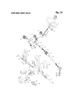
Страница 51: ...Fig 19 STEERING SHAFT ASSY...

Страница 52: ...215 COTTER PIN 2x15 2 24 7 020 066 STEERING KNUCKLE DUST COVER 2 25 8 020 014 STEERING GEAR BRACKET 2 26 9 220 008 LOCKING FLANGE NUT M8 8 27 9 708 145 THROTTLE PEDAL BOLT M8 x 1 25 x 145 1 28 8 040...

Страница 53: ...Fig 20 FRONT SUSPENSION ARM ASSY...

Страница 54: ...0 028 FRONT BRAKE CALIPER L 1 17 8 010 054 BRAKE DISC 2 18 9 040 002 DUST SEAL 47x25 7 2 19 9 030 002 Z BEARING 6204 Z 2 20 9 710 031 TIRE BOLT M10x1 25x31 8 21 8 010 085 WHEEL HUB 2 22 9 030 010 Z BE...

Страница 55: ...Fig 21 FULL SHIFTING ASSY...

Страница 56: ...LT WASHER M10 x 1 25 x 200 1 13 9 220 010 LOOKING FLANGE NUT M10 5 14 6 000 237 PIVOT ARM SHIFT A 1 15 7 010 004 PEDAL BUSH 2 16 9 108 145 BOLT M8x1 25x145 1 17 6 000 235 RIGHT TURN CLEVIS ROD HEAD 1...

Страница 57: ...REAR CARGO RACK SEAT BELT Fig 22...

Страница 58: ...x 1 25 x 25 4 14 8 010 034 TANK COMP COLLAR 4 15 7 020 005 RUBBER MOUNT 4 16 9 300 008 FLAT WASHER 8 4 17 6 000 046 FUEL AUTO COCK ASSY 1 18 6 000 056 GAS FILTER 1 19 7 020 030 TUBE COMP FUEL 1 1 20 7...

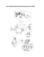
Страница 59: ...FIG 23 AIR CLEANER RADIATOR BATTERY MUFFLER ASSY...

Страница 60: ...12 7 090 044 TUBE CLAMP 4 13 7 090 045 TUBE COMP WATER 3 1 14 7 090 046 TUBE COMP WATER 4 1 15 9 100 830 BOLT M8x 30x1 25 2 16 7 090 047 RADIATOR COMP COLLAR 2 17 7 020 069 RUBBER MOUNT 2 18 9 200 008...

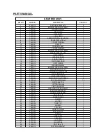
Страница 61: ...FIG 24 GEAR BOX ASSY...

Страница 62: ...25x4 1 21 7 090 017 BEARING RADIAL BALL E6204 1 22 9 040 013 DUST SEAL 42 x 25 x 8 1 23 7 090 018 LOCKING PIN IN OUT 4x8 1 24 7 090 019 PIVOT GEAR SHIFT 1 25 8 030 041 L SIDE CASE COVER 1 26 7 090 020...

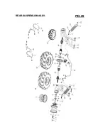
Страница 63: ...FIG 25 REAR SUSPENSION ASSY...

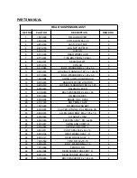
Страница 64: ...FLANGE NUT M10 x 1 25 2 16 6 000 243 BALANCE LEVER 1 17 9 108 020 BOLT WASHER M8 x 20 x 1 25 4 18 8 010 053 RR BRAKE DISC 1 19 8 030 036 BRAKE DISC BASE 1 20 9 101 018 BOLT MlOx 1 5x18 1 21 7 020 022...

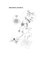
Страница 65: ...WIRE HARNESS ELECTRICAL...

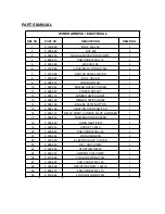
Страница 66: ...SWITCH UNIT 1 13 6 000 160 DIMMER SWITCH UNIT 1 14 6 000 159 ENGINE STOP BUTTON 1 15 6 000 158 IGNITION START SWITCH 1 16 6 000 153 RELAY COMP AUDIBLE PILOT WINKER 1 17 6 000 251 TEMPERATURE BUZZER 1...

Страница 67: ...CASE 1 4 9 090 010 LABEL NO LONG HAIR 1 5 9 090 011 LABEL WARNING 1 6 9 090 012 LABEL NO CLIMBING 1 7 9 090 013 LABEL WARNING 1 8 9 090 014 LABEL SEAT BELT 1 9 9 090 024 LAB EL RADIATOR 1 10 9 090 016...

Отзывы: