Document #101-0240
6
04/22/2013
III. OPERATION
To dispense the coins, the Hopper uses a Coin Wheel mounted to the Hopper Motor. This Coin Wheel is a round
disc with semi-circular cutouts arranged around the outer edge. As the wheel rotates with the motor, coins fall
into the cutouts and are lifted past the count switch and through the exit chute. If coins are picked up in every
cutout, a dispensing rate of 5 coins per second is achieved.
The Coin Counting Mechanism utilizes a pair of switches that are actuated by coins as they exit the Hopper.
One switch directly triggers the 120VAC counter mounted on the Hopper. The other switch manipulates the
controllers “Coin Drop” input. The normally closed contacts are opened as a coin passes under the switch. This
opening of the “Coin Drop” circuit is observed as a coin vends.
The Coin Level Mechanism takes advantage of the conductivity of metallic coins. Since the Coin Wheel is
connected to earth, and logic grounds through the case of the motor, a connection can be made from the Coin
Wheel through the coins to the stainless sensing that are connected to the Controller. When the coins no longer
touch the sensing strips, the circuit is open and the Hopper is observed as empty. When the Hopper does go
empty, there will still be approximately 70-125 quarter sized coins left in the Hopper Bowl. Note: this number
will vary based on the coin size being dispensed.
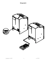
Diagram A on page 12 indicates where the “Manual Run” Toggle Switch is located. Also pictured in Diagram
A this the bracket that encases the Toggle Switch. There is also a thumbscrew that fits into this bracket and
prevents the switch from being activated. The thumbscrew must be removed and the Toggle Switch flipped to
its “ON” position. To stop the motor, turn the “Manual Run” Toggle Switch back to its “OFF” position and re-
insert the thumbscrew.
Note: In several of Hamilton’s changers the main harness has a single quick disconnect connector that disables
the hopper run switch. If the manual run switch is required connect connector, otherwise it is Hamilton’s recom-
mendation that the connector should remain disconnected when hopper run switch is not required.
The “Smart Hopper” has a few variations. The first one is that the Smart Hopper only has “ONE” coin count-
ing this switch. This is the switch that manipulates the controllers “Coin Drop” input. The second switch on
the Smart Hopper is not required because there is no counter on the hopper. The other variation is there is no
“Manual Run” Toggle Switch, therefore shown on Diagram A on page 12 will show where to connect the Hand-
held. The Handheld function allows one to conduct a “Manual Run”, show counters, clear counters, and conduct
maintenance (clear errors).
Содержание Hopper HSH
Страница 1: ...Document 101 0240 1 04 22 2013 Hamilton Hopper Manual ...
Страница 12: ...Document 101 0240 12 04 22 2013 Diagram A ...
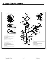
Страница 16: ...Document 101 0240 16 04 22 2013 HAMILTON HOPPER ...
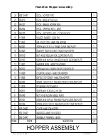
Страница 17: ...Document 101 0240 17 04 22 2013 Hamilton Hopper Assembly ...
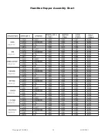
Страница 18: ...Document 101 0240 18 04 22 2013 Hamilton Hopper Assembly Chart ...
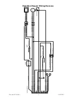
Страница 19: ...Document 101 0240 19 04 22 2013 Hamilton Hopper Wiring Harness ...
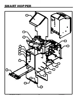
Страница 20: ...Document 101 0240 20 04 22 2013 SMART HOPPER ...
Страница 21: ...Document 101 0240 21 04 22 2013 Smart Hopper Assembly ...
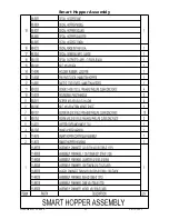
Страница 22: ...Document 101 0240 22 04 22 2013 Smart Hopper Assembly Chart ...
Страница 23: ...Document 101 0240 23 04 22 2013 Smart Hopper Wiring Harness ...
Страница 24: ...Document 101 0240 24 04 22 2013 HOPPER BOWL ...
Страница 25: ...Document 101 0240 25 04 22 2013 Hopper Bowl Assembly ...


