


9
Subject to change without notice
probe can be compensated by a higher amplitude setting, the
probe should always be used. The series impedance of the
probe provides a certain amount of protection for the input of
the vertical amplifier. Because of their separate manufacture,
all attenuator probes are only partially compensated, therefore
accurate compensation must be performed on the oscilloscope
(see Probe compensation ).
Standard attenuator probes on the oscilloscope normally reduce
its bandwidth and increase the rise time. In all cases where the
oscilloscope bandwidth must be fully utilized (e.g. for pulses
with steep edges) we strongly advise using the probes
HZ51
(x10)
HZ52
(x10 HF) and
HZ54
(x1 and x10). This can save the
purchase of an oscilloscope with larger bandwidth.
The probes mentioned have a HF-calibration in addition to low
frequency calibration adjustment. Thus a group delay correction
to the upper limit frequency of the oscilloscope is possible with
the aid of an 1MHz calibrator, e.g.
HZ60
.
In fact the bandwidth and rise time of the oscilloscope are not
noticeably changed with these probe types and the waveform
reproduction fidelity can even be improved because the probe
can be matched to the oscilloscopes individual pulse response.
If a x10 or x100 attenuator probe is used, DC input
coupling must always be used at voltages above 400V.
With AC coupling of low frequency signals, the
attenuation is no longer independent of frequency,
pulses can show pulse tilts. Direct voltages are
suppressed but load the oscilloscope input coupling
capacitor concerned. Its voltage rating is max. 400 V
(DC + peak AC). DC input coupling is therefore of quite
special importance with a x100 attenuation probe which
usually has a voltage rating of max. 1200 V (DC + peak
AC). A capacitor of corresponding capacitance and
voltage rating may be connected in series with the
attenuator probe input for blocking DC voltage (e.g. for
hum voltage measurement).
With all attenuator probes, the maximum AC input voltage
must be derated with frequency usually above 20kHz. Therefore
the derating curve of the attenuator probe type concerned
must be taken into account. The selection of the ground point
on the test object is important when displaying small signal
voltages. It should always be as close as possible to the
measuring point. If this is not done, serious signal distortion
may result from spurious currents through the ground leads or
chassis parts. The ground leads on attenuator probes are also
particularly critical. They should be as short and thick as
possible. When the attenuator probe is connected to a BNC-
socket, a BNC-adapter, should be used. In this way ground and
matching problems are eliminated. Hum or interference
appearing in the measuring circuit (especially when a small
deflection coefficient is used) is possibly caused by multiple
grounding because equalizing currents can flow in the shielding
of the test cables (voltage drop between the protective
conductor connections, caused by external equipment
connected to the mains/line, e.g. signal generators with
interference protection capacitors).
Controls and readout
The following description assumes that the operating mode
“COMPONENT TEST” is switched off. All important measuring
parameter settings are displayed in the screen readout when
the oscilloscope is on.
The LED indicators on the large front panel facilitate operation
and provide additional information. Electrical end positions of
controls are indicated by acoustic signal (beep).
All controls, except the power switch (POWER), the calibration
frequency pushbutton (CAL. 1kHz/1MHz), the FOCUS control
and the trace rotation control, are electronically set and
interrogated. Thus, all electronically set functions and their
current settings can be stored and also remotely controlled.
Some controls are only operative in the digital mode or have a
different function. Explanations pertaining to them are indicated
with the hint “storage mode only”.
The large front panel is, as is usual with Hameg oscilloscopes,
is marked with several fields.
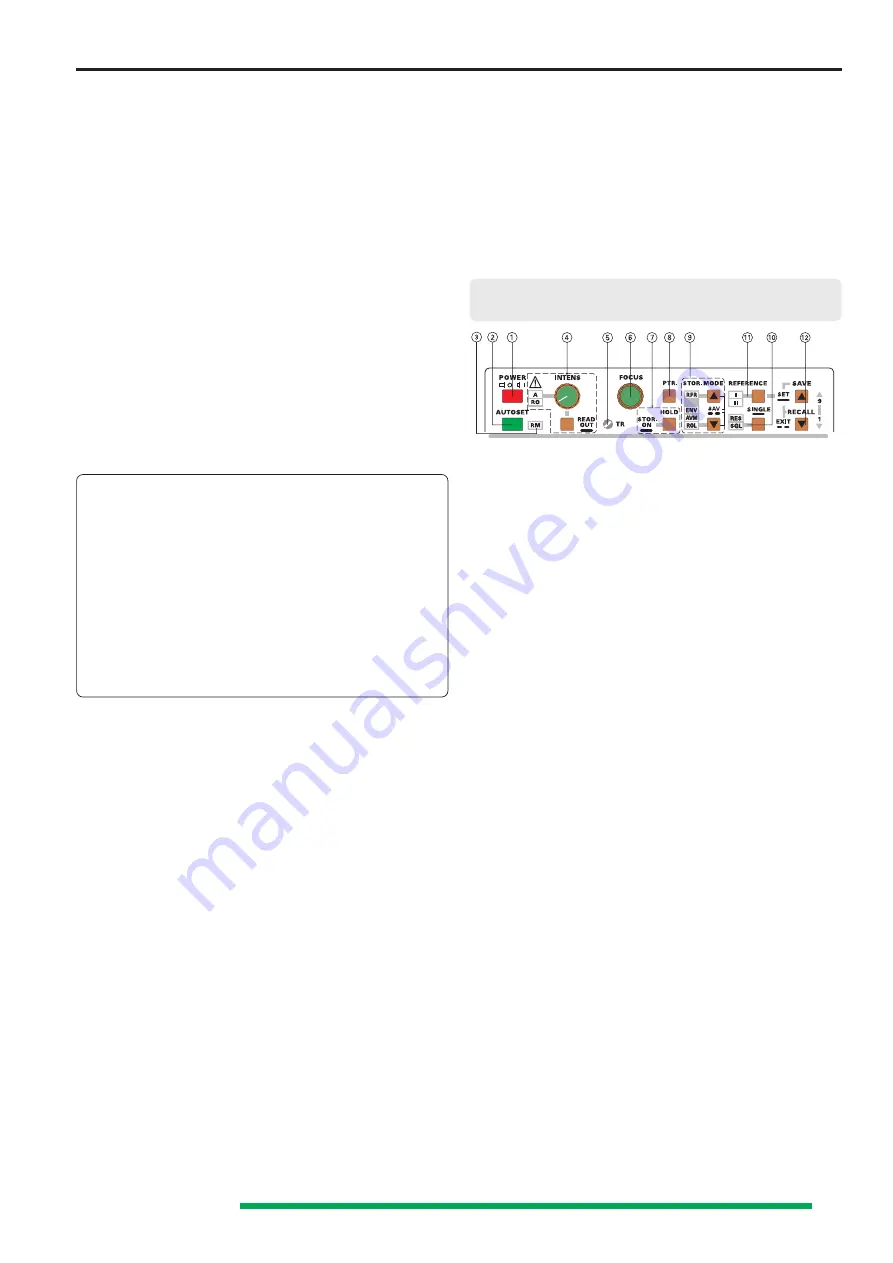
The following controls and LED indicators are located on the
top, to the right of the screen, above the horizontal line:
(1)
POWER
- Pushbutton and symbols for
ON (I)
and
OFF (O)
.
After the oscilloscope is switched on, all LEDs are lit and
an automated instrument test is performed. During this
time the
HAMEG
logo and the software version are
displayed on the screen. After the internal test is completed
successfully, the overlay is switched off and the normal
operation mode is present. Then the last used settings
become activated and one LED indicates the ON condition.
It is possible to modify certain functions (SETUP) or to call
automatic calibration procedures (CALIBRATE).
For details
relating to this see section “MENU”.
(2)
AUTOSET
- Pushbutton
Briefly depressing this pushbutton results in an automatic
instrument setting automatically selecting Yt mode. The
instrument is set to the last used Yt mode setting (
CH I
,
CH II
or
DUAL
).
SEARCH (SEA)
and
DELAY
(
DEL
and
DTR
) mode is
automatically switched off.
Please note “AUTO SET”.
Automatic CURSOR supported voltage measurement
If
CURSOR
voltage measurement is present, the
CURSOR
lines are automatically set to the positive and negative
peak value of the signal. The accuracy of this function
depends on the signal frequency and is also influenced by
the signal‘s pulse duty factor. If the signal height is
insufficient, the
CURSOR
lines do not change. In DUAL
mode the
CURSOR
lines are related to the signal which
is used for internal triggering.
STORAGE MODE ONLY
Additionally,
AUTO SET
automatically selects refresh
mode
(RFR)
when
SINGLE (SGL)
or
ROLL (ROL)
function
is in operation.
Automatic CURSOR supported measurement
In contrast to analog mode,
AUTO SET
also causes an
automatic
CURSOR
line setting if time or frequency
measurement has been selected and at least one signal
period is displayed. Neither the signal frequency nor the
pulse duty factor have an effect on the accuracy when
CURSOR voltage measurement is chosen.
(3)
RM - LED
The remote control mode can be switched on or off
(
”RM”
LED dark) via the RS232 interface. On condition
Controls and readout


