Instruction Manual HIPERDRIVE with EtherCAT
27
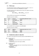
5.3 PDO format
The following table describes the PDOs for the first drive connected, i.e. drive 1 on
the hub or the drive connected to the HIPERDRIVE bus adapter.
The PDO information for each additional drive (on the hub) is attached in each case,
i.e. the following applies:
Byte number
Drive n
= Byte number
Drive 1
+ (n - 1) * 8
1) Receive PDO (from the perspective of the HIPERDRIVE)
Assignment (cannot be modified):
Bit
Byte
Meaning
Corresponding SDO index number
0-15
0,1
Control word
2080h
16-23
2
Percentaged target
speed
2081h
24-31
3
Percentaged
maximum torque
2082h
32-63
4-7
Target position
2083h
2) Transmit PDO (from the perspective of the HIPERDRIVE)
Assignment (cannot be modified):
Bit
Byte
Meaning
Corresponding SDO index number
0-15
0,1
Status
2084h
16-31
2,3
Current r.p.m.
2085h
32-63
4-7
Actual position
2086h
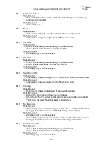
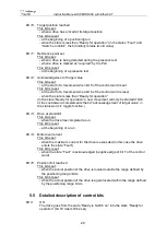
5.4 Detailed description of status bits
The functions of the status and control bits are based on the PROFIDRIVE protocol:
Bit 0
:
Ready to switch on
This bit is set:
- when bit 10 of the control word is set (set control word to 0x0400)
This bit is reset:
- when bit 10 is reset (set control word to 0x0000)
Bit 1
:
Ready for operation
This bit is set:
- when bit 0 of the control word
is set in the state “Ready to Switch on” (set
control word to 0x0401)
This bit is reset:
- when bit 0 is reset


