Supplied By www.heating spares.co Tel. 0161 620 6677
24
26
INSTALLING THE FLUE SYSTEM FROM
INSIDE THE ROOM
25
4.7.2
FLUE RESTRICTOR
4.7.3
INSTALLING THE AIR/FLUE DUCT
FROM INSIDE THE ROOM
A flue restrictor is supplied with the appliance for use, only if
no extensions or additional flue extension elbows are fitted.
If any extension ducts or additional elbows etc are to be used,
proceed to section 4.7.3.
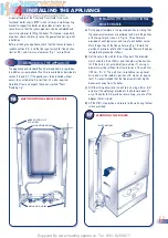
If only the standard flue components (i.e. those packed in the same
carton as the appliance) are to be used fit the restrictor as follows:
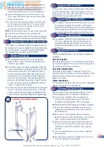
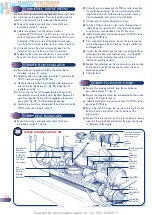
a)
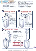
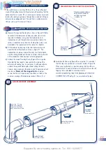
Note the position of the flue restrictor ring. This is fitted on top
of the appliance and is secured by the air pressure switch
bracket screws (Fig. 24). Loosen the air pressure switch screw
by 1/2 turn only, to release the ring, and tighten the two screws.
b)
Fit the restrictor ring inside the flue elbow bottom as shown in
figure 25 ensuring that it is the correct way round.
NOTES
(i)
Failing to fit the restrictor when installing the appliance with a
standard flue system will not provide optimum appliance performance.
(ii)
Fitting the restrictor on a flue system incorporating extensions
or additional bends will adversely affect performance and
may constitute a safety hazard.
(iii)
Failing to comply with these instructions will invalidate the
appliance Certification and therefore may contravene the
appropriate EC legislation and local statutory requirements.
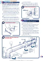
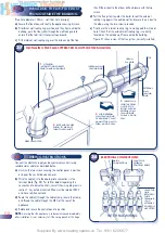
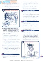
Wall thickness up to 800 mm (31in) only.
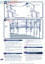
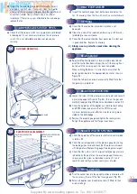
a)
Push the terminal through the wall liner taking care to ensure
that the terminal is the correct way round and the external
wall sealing ring does not become dislodged.
b)
Pull the flue system towards the boiler to seat the external
sealing ring against the outside wall and secure the elbow to
the boiler using the two screws provided.
c)
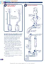
Finally use the internal sealing ring to make good the internal
hole, and check that the terminal is correctly located on the
outside wall (Where possible this should be visually checked
from outside the building.) Figure 26 shows a view of the flue
system, correctly installed.
d)
Assemble as shown in Figure 26
•
•
•
•
•
2
ALIGN ASSEMBLED
FLUE SYSTEM ELBOW TO
APPLIANCE AND SECURE
3
SLIDE INTERNAL
WALL SEALING RING
TO WALL TO FORM
A GOOD SEAL
1
INSERT
ASSEMBLED FLUE
SYSTEM FROM
INSIDE THE ROOM.
EXTERNAL WALL
SEALING RING
OPENS
•
EXTERNAL
WALL
SEALING
RING
130mm Dia.
HOLE WITH
WALL LINER
INTERNAL WALL
SEALING RING
FITTING THE FLUE RESTRICTOR
•
FLUE
RESTRICTOR
•
APPLIANCE TOP
TOP
FLUE RESTRICTOR LOCATION
(Do not disturb if extension ducts are to be fitted)
•
FIBRE
SEAL FITTED
90° ELBOW
ALUMINIUM
FAN OUTLET
RESTRICTOR
FAN
•
•
•
17


