background image


MAN1565-4 


31


6.16


Agent Release Module 

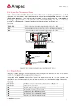
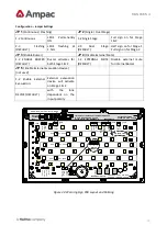
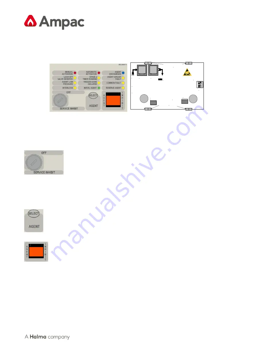
The Agent Release Module controls and monitors all the requirements for agent release and carries the slide in label 
for identification of the agent and application area. 


K1 Termination Link

In

Out

Address 
 Switch
Set to 1

CN6: Communications & +27V IN from CN2 off the
Previous Front Panel Module or CN9 on the Main Card

CN7: Communications & 27V OUT to Next Front Panel
Card. If Unsed the Termination Link Must be Inserted.

Top Module & PCB

Securing Clips

Bottom Module & PCB

Securing Clips

SW2

CN2

CN7

CN6

TP

9

Key Switch

RS485 
    & 
+/- 27v
   In

RS485 
    & 
+/- 27v
  Out

1


2


3

  4

ON

CN8
Manual Release


Figure 23: Exploded View of Module and Front Panel Layout 

The  PCB  is  fitted  with  two  2  x  RJ45  connectors  CN6  &  7  for  power  (27VDC)  and  communications  (RS485)  for 
communications between the Agent Release Module and the FACP Main Control Board. 

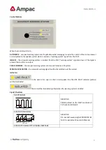
Controlled Access 

 It is a requirement that control be secured from unauthorised use. A keyswitch has therefore 

been included in the control process. 

The FCP goes into service mode when the keyswitch is switched to SERVICE INHIBIT. This results in the selected agent 
activation  circuit  being  electrically  isolated  and  a  Common  Isolate  condition  being  indicated  at  the  FACP.  This 
condition can also be confirmed through the Status Menu. To remove the key it is necessary for the switch to be in the 

OFF

 position. 

 Pressing Select toggles the selection of either the Main or Reserve release agent. Selection is indicated by 

the Main and Reserve Agent LED’s


  If  activated  the Manual  Release  will  commence  the  discharge  sequence  of  the  selected  agent  and  an 

alarm condition is initiated. Progress of the release can be monitored through the Status Menu. To prevent accidental 
operation this switch has a hinged clear plastic cover that has to be raised to access the switch. 

Quiescent Current: 28.5mA 

Note:


If the keyswitch is not used CN2 will carry a link so as to enable the panel.


Содержание ZoneSense Plus AS

Страница 1: ...Fire detection and evacuation solutions that save lives ZoneSense Plus AS Installation Commissioning of Control Monitoring Add Ons MAN1565 4 ...

Страница 2: ...s 13 6 4 Links and Settings 14 6 5 8 Way Switch and Indicator Card 15 6 6 16 Way Input Board 16 6 7 8 Way Relay Board 17 6 7 1 Internal Relay Board 17 6 7 2 Remote Relay Board 18 6 8 8 Way Sounder Board 19 6 9 4 Way Fire Fan Module 20 6 10 4 Way Fan Termination Board 21 6 11 Brigade Board 21 6 11 1 Brigade Connections 23 6 12 General Indicator Card 24 6 13 LED Annunciator Master LAM 25 6 14 Agent ...

Страница 3: ...s should Be qualified and trained for the task they undertake Be familiar with the contents of this manual prior to the installation commissioning or operation of a ZoneSense PLUS control system Observe anti static pre cautions at all times and Be aware that if a problem is encountered or there is any doubt with respect to the operational parameters of the installation the supplier should be conta...

Страница 4: ...ys are also used for panel operation and interrogation Four monitored conventional Alarm circuits Two optional auxiliary input connections Two open collector outputs fire and fault Two relay outputs ancillary and fault Optional external buzzer or reset output System expansion capabilities options Password entry to a wide range of programming and diagnostic functions which include Zone configuratio...

Страница 5: ...oard and a power supply unit The main board provides The visual indication and control Two Relays with volt free Alarm and Fault changeover contacts Termination for zones Monitored outputs Power supply monitoring RS485 communications port The ZoneSense PLUS can be quickly converted to an AS4214 approved Agent Release System with the use of the Agent Release Module and if required a remote Local Co...

Страница 6: ...at the cable remains connected to at least one board to prevent it being misplaced Note Care should be taken when detaching this connector as it is necessary to depress the small locking tab to unlock the connector from its base To reconnect the cable the connector must first be correctly aligned then pushed into the socket so it locks into position Carefully remove the retaining screws at each co...

Страница 7: ...Acknowledge Fault Reset Isolated Isolate De isolate Fault Isolate Alarm ZONE 1 ZONE 2 ZONE 3 ZONE 4 ZONE 5 ZONE 6 ZONE 7 ZONE 8 ACF Isolate Cancel Menu Enter RELAY OUTPUTS Figure 3 Main Control Card Front PCB View CN5 Comms 27VDC 400mA Current Limit To Backpan Boards If the FACP Backpan Configuration Exceeds 400mA the 27VDC MUST BE TAKEN FROM CN10 CN9 Comms 27VDC To Any Cards Fitted To The Front P...

Страница 8: ...nitoring Comms from the Power Supply Pins 0V PSU Sense PSU Adjust Charger ON Batt Load Temp sense Batt V Sense CN7 Factory Use Only CN8 27V and earth from the Power Supply Charger Pins 0V 27V Earth CN9 Comms to the internal front panel cards Imax 400mA Pins Pin connections are the same as CN5 CN10 27V and 0V to the Sounder Agent Release and Fan Termination back plan boards Imax P S limit All other...

Страница 9: ...5 2 10 Zone 5 3 11 Zone 6 4 12 Zone 6 5 13 Zone 7 6 14 Zone 7 7 15 Zone 8 8 16 Zone 8 MONITORED OUTPUTS 500mA O p TB4 1 17 External Bell 2 18 External Bell 3 19 Warning System 4 20 Warning System 5 21 ACF Aux Control Function 6 22 ACF 7 23 ASE Alarm Signaling Equipment 8 24 ASE OPEN COLLECTOR OUTPUTS 30 mA O P TB5 1 25 Alarm 2 26 Alarm 3 27 Fault 4 28 Fault OUTPUTS VOLT FREE RELAY 1A 30V 5 29 NO A...

Страница 10: ...V 500mA O P 24v 100mA 0v 12v Batt 12v Batt BATT DC OUTPUT OV 27V GND 1 2 1 2 6 8 4 3 5 7 TO THERMISTOR EXTENSIONS OF PIN 1 TEMPSENSE RTN AND PIN 6 TEMPSENSE OF RJ45 RJ 45 PINOUT CONNECTIONS 1 TEMP SENSE RTN 2 SUPPLY SENSE 3 PSU V ADJ 4 CHARGER ON 5 LOAD ON 6 TEMPSENSE 7 BATTERY V SENSE 8 OV 1 2 3 CN2 CN5 CN5 CN2 LED CN4 CN3 Power Supply Unit PSU Rear of Main Card Front of Main Card Illustrated Ext...

Страница 11: ... and mimics up to a distance of 1 2km from the FACP The external cabling 1 pair twisted shielded cable plus power is wired to TB2 and earth Note If a fault occurs on the communications line the common FAULT and SYSTEM FAULT LED S will be illuminated Selecting the Faults Menu will display the fault details on the LCD 5 4 1 Main Card Comms Link K1 K1 MUST be inserted when Front door panel cards and ...

Страница 12: ...rface Board BRD25BBA Agent Release Control consists of a Termination Board BRD25ATB and front panel card BRD25ARB General Indicator Card BRD25GIB A LED Annunciator Master BRD25GIB E Occupant Warning System EV20 EV40 EV60 and EV120 Note To add or remove Add On s from the FACP go to the SYSTEM and PROGRAM Menus Note Refer to manual MAN1564 ZoneSense Plus 2008 AS programming for instructions on progr...

Страница 13: ...ONAL BRIGADE BOARD CAB2200 CAB2200 BRD25ARB PCB0783 AGENT RELEASE MODULE BRD25ATB PCB0787 AGENT TERMINATION BOARD BRD25BBA PCB0779 BRIGADE BOARD BRD25EWRB PCB0770 8 WAY RELAY BOARD BRD25FCB PCB0783 FIRE FAN MODULE BRD25FTB PCB0780 FAN TERMINATION BOARD PSU1887 C N3 C N4 C N3 C N4 C N3 C N4 BRD25GIB PCB0781 GENERAL INDICATOR CARD BRD25MCB PCB0769 MAIN CONTROL CARD BRD25PSU PCB0813 POWER SUPPLY UNIT...

Страница 14: ...mber of LED Mimics in the system The information at each location will be identical Address Setting DIL Switch ON 1 OFF 0 Address 1234 Address 1234 01 1000 05 1010 02 0100 06 0110 03 1100 07 1110 04 0010 08 0001 1 2 3 4 On Figure 8 Example of Switch Set to 1 LK1 on Each Board LK1 is the EOL Link and MUST be inserted on the last board on each communications bus If not communications faults can occu...

Страница 15: ...ng the button once will cause a condition to be held until the button is pressed again The associated LED is not available as an output in C E and shall always be illuminated when the toggle condition is active Also when configured as a toggle there shall be an option for a timer override If the toggle switch is activated it shall be de activated automatically after the timeout period Fit EOL Term...

Страница 16: ...ule on Comms Bus Address SW SET to 1 INPUTS 1 2 3 4 0V INPUTS 5 6 7 8 0V INPUTS 9 10 11 12 0V INPUTS 13 14 15 16 0V 0V Not used optional 27V TB9 TB8 TB7 TB6 TB5 TB4 TB3 RS485 Control 27VDC Comms Out CN2 CN1 CN3 CN4 TB2 1 2 3 4 ON ON RS485 Control 27VDC Comms In INPUTS 1 2 3 4 INPUTS INPUTS INPUTS 0V TB9 TB8 TB7 TB6 TB5 TB4 TB3 TB2 0V 5 6 7 8 0V 9 10 11 12 0V 13 14 15 16 0V Figure 10 Typical Input ...

Страница 17: ...conds when reset depressed 6 7 1 Internal Relay Board Fit EOL Termination Link 1 if Last Module on Comms Bus Address SW SET to 1 Not used optional 27VDC RS485 Control 27VDC Comms In CN2 CN1 CN3 CN4 ON TB8 TB7 TB6 TB5 TB4 TB3 TB2 TB1 SW1 O P 8 N C COM N 0 O P 7 N C COM N 0 O P 6 N C COM N 0 O P 5 N C COM N 0 O P 4 N C COM N 0 O P 3 N C COM N 0 O P 2 N C COM N 0 O P 1 N C COM N 0 1 2 3 4 O N TB8 TB7...

Страница 18: ... COM N 0 O P 2 N C COM N 0 O P 1 N C COM N 0 N 0 Normally Open COM Common N C Normally Closed TB8 TB7 TB6 TB5 TB9 TB4 TB3 TB2 TB1 SW1 TB10 O P 8 N C COM N 0 O P 7 N C COM N 0 O P 6 N C COM N 0 O P 5 N C COM N 0 O P 4 N C COM N 0 O P 3 N C COM N 0 O P 2 N C COM N 0 O P 1 N C COM N 0 RS485 RS485 SHD RS485 COMMS IN OUT Address SW To TB3 on the Main Card and or Zone Mimic Card 1 2 3 4 ON 27 Volts Out ...

Страница 19: ...8 DC IN 0V 27V Fit EOL Termination Link 1 if Last Module on Comms Bus Address SW POWER CN2 CN1 27V To Sounders 1 to 4 To Sounders 5 to 8 1 2 3 4 O N TB2 TB1 VE VE SOUNDER 1 VE VE SOUNDER 2 VE VE SOUNDER 3 VE VE SOUNDER 4 VE VE SOUNDER 5 VE VE SOUNDER 6 VE VE SOUNDER 7 VE VE SOUNDER 8 To Sounders 1 to 4 To Sounders 5 to 8 RS485 Control Comms In ON 27VDC Out CN3 CN4 TB3 DC IN 0V 27V POWER 27V EOL Re...

Страница 20: ...n label can also be inserted into the hinged cover for identification purposes The Plant Trip Reset is used to locally restart plant and equipment that has been automatically shut down because the FACP has initiated an alarm once that alarm has been cleared Quiescent Current 13 5mA Fit EO Termination Link 2 if Last Module on Comms Bus In Out Address Switch Set to 1 1 2 3 4 ON C N 1 C N 2 RS485 Con...

Страница 21: ...RT FAN 4 STOP START FAN 2 CN1 CN2 CN3 CN4 RS485 Control Comms In STOP COM STOP FLT RUN START TB 2 3 4 or 5 Cabling from the FACP to the Plant Equipment START FAN CONTROL RELAY INTERFACE FAN MONITORING RUN RS485 Control Comms Out 27VDC Out 27VDC In SW1 Address SW 1 2 3 4 ON ON Fit EOL Termination Link if Last Module on Comms Bus START RUN FLT STOP COM Figure 15 Fan Termination Board Layout and Typi...

Страница 22: ...ALARM 1 N 0 COM N C FAULT N 0 COM N C ISOLATE N 0 COM N C BATT FAIL N 0 COM N C ALARM 2 C N 2 C N 1 CN3 CN4 1 2 3 4 ON POWER 0V 27V N 0 Normally Open COM Common N C Normally Closed TB5 TB4 TB3 TB2 TB1 N 0 COM N C ALARM 1 N 0 COM N C FAULT N 0 COM N C ISOLATE N 0 COM N C BATT FAIL N 0 COM N C ALARM 2 Wired To the Appropriate Relay or Interface N O COM N C Figure 16 Brigade Board Overlay ...

Страница 23: ... BRIGADE BOARD IS NORMALLY ENERGISED DURING NORMAL OPERATION OF THE SYSTEM HENCE TB10 2 3 WILL PRESENT AN O C TO THE I F 1A RL 1 COMMON 27 VDC BLACK ASE FAULT CN6 5 6 RL 1 RED YELLOW BLUE Figure 17 ASE FACP Internal Wiring The Brigade Box interfaces the Fire Brigade to the LoopSense series of FACP s RED BLACK BRIGADE BOX BACKPAN TELEPHONE CABLE IN TB6 3 2 ALARM FAULT ISOL TB8 3 2 TB3 3 2 N C COM N...

Страница 24: ...ble tri coloured LED s The function is identified on the front panel by slip in labels whose lettering must no smaller than 3 mm Quiescent Current 3 6mA depending on the application K2 Termination Link In Out Address Switch Set to 1 1 2 3 4 ON C N 1 C N 2 CN1 Communications 27V IN from CN2 off the previous Front Panel Card or CN9 on the Main Card CN2 Communications 27V OUT to Next Front Panel Card...

Страница 25: ...0V 24V COM SHLD RS485 AUX 24VDC RS 485 IN FROM FACP PWR OUT PWR IN 0V 24V COM RS 485 OUT TO NEXT LAM LINK TERMINATOR LK1 CN6 ON 1 2 3 4 0V 24V COM RS 485 IN FROM PREVIOUS LAM PWR IN 0V 24V COM LINK TERMINATOR LK1 CN6 ON 1 2 3 4 0V 24V COM ONLY INSERTED ON THE LAST CARD RS 485 IN FROM PREVIOUS LAM PWR OUT PWR IN 0V 24V COM RS 485 OUT TO NEXT LAM LINK TERMINATOR LK1 CN6 ON 1 2 3 4 0V 24V COM RS 485 ...

Страница 26: ...isolate condition on any zone device or output AMBER Illuminated flashing at the fault rate by an open or short circuit condition on the FACP bell output Indicator will extinguish when the open or short condition has cleared AMBER Illuminated flashing at the fault rate by an open or short circuit condition on the FACP warning system output Indicator will extinguish when the open or short circuit h...

Страница 27: ...ed Pressure Switch PSW is wired to the PSW input on the Termination Board and is used to confirm that the agent has been released The circuitry involved in this process can be configured to accept a normally open contact normally closed contact normally open mechanically operated manual or is ignored not fitted and is selected via FACP on site programming If the mechanical manually operated option...

Страница 28: ...O NOT ENTER signs illuminated aural alarm sounds Optional pre release delay is started Selected via FACP on site programming The delay times out and if the Interlock signal is ON the selected circuit will activate The Pressure Switch field input on the Termination Board is activated and the Agent Discharge LED on the Agent Release Module and Local Control Station will be illuminated Activate gas f...

Страница 29: ...ms A Zone Fault A Fault on the interlock input A Fault with a LCS Note 1 The common fault indicator on the Agent Release Module and Local Control Station is illuminated for any Fault condition Note 2 For a pressure switch fault low pressure switch fault lock off valve fault stage 1 output fault stage 2 output fault and interlock fault the FACP will signal the brigade Note 3 When there is a fault i...

Страница 30: ... relay is output closed Stage 2 output is switched to 24VDC and stage 2 relay output is closed Light the agent release led on the ACC and LCS s Activate gas fired relay output Monitoring of the Pressure Switch Due to the requirements of Manual Mechanical Release of the Agent the pressure switch input conveys two pieces of information When the pressure switch input is active it signals that the age...

Страница 31: ...Access It is a requirement that control be secured from unauthorised use A keyswitch has therefore been included in the control process The FCP goes into service mode when the keyswitch is switched to SERVICE INHIBIT This results in the selected agent activation circuit being electrically isolated and a Common Isolate condition being indicated at the FACP This condition can also be confirmed throu...

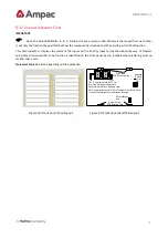
Страница 32: ...th 10KΩ EOL This input is used to determine if air conditioning dampers and doors are closed but can be defaulted to the ON condition by terminating the input with a 2K2Ω EOL Double action switching is achieved by way of protective lift up covers seen here and manual operation of the MCP or Inhibit switch To ensure correct operation and prevent accidental release of the agent these covers should n...

Страница 33: ...thermal switch If there is no pressure switch fitted the indicator shall be illuminated immediately the agent release signal is activated Selected via FACP on site programming refer to relevant FACP Manual The indicator is extinguished by activating RESET on the FACP LOCK OFF VALVE INHIBITED Yellow Illuminated when the lock off valve has been activated STAGE 2 TIMER RUNNING Yellow Illuminated when...

Страница 34: ...fault conditions and can be silenced by using the appropriate FACP buzzer silence control When the LCS Inhibit control is activated after 8 hours treated as an isolate condition When the service inhibit is activated after 8 hours treated as an isolate condition Connecting the LCS to the Agent Termination Board ISOLATE THE AGENT Check the FACP is functioning correctly then power down Connect the LC...

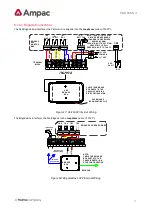
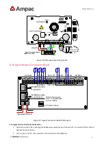
Страница 35: ...MMS BUS Figure 26 PCB Layout Cabling Details 6 18 Agent Release Termination Board SW1 LOCK L PSW RELEASE SIG SIG LCS CABLE PSW INPUTS N 0 STAGE2 GAS N 0 COM N 0 COM SYST SCRN 24VDC 0VDC STAGE1 COM TB7 TB6 TB5 TB4 TB3 TB2 TB1 C N 2 C N 1 Address Setting CN3 CN4 RS485 Control Comms In MAIN RESV Outputs are Monitored Fit EOL Termination Link 1 to Last Module on Comms Bus 1 2 3 4 ON INOP FIRED MONITOR...

Страница 36: ...ontacts wired to TB6 3 4 8 Release Main actuating circuit monitored 10KΩ EOL required via TB7 1 2 2A current limited 9 Release Reserve actuating circuit monitored 10KΩ EOL required via TB7 3 4 2A current limited Metron Igniters max of 10 a series 2watt 18 resister must be added to the circuit Solenoid valve max current of 2 amps 27VDC 6 18 1 Interface Wiring Monitored Inputs TB2 1 2 Solenoid Metro...

Страница 37: ...6 Stage 1 is Stage 2 is Figure 31 Stage 1 and 2 Wiring 6 18 2 Warning Signs Description The warning signs are driven by a 2 wire system and may be configured for single or dual stage operation An on board buzzer provides an audible warning which may be disabled by removing JP3 External evacuation devices e g sounders may be connected to TB3 of the input termination board An external mute push butt...

Страница 38: ...sure to ensure it is not damaged while mounting the enclosure Bring the cabling into the enclosure by removing the knockouts most appropriate for the installation Mount the enclosure remount the back pan set the configuration and then cable as per the following diagram ENSURE THE AGENT IS ISOLATED and test from the Agent Release Module Cabling Term 3 Buzzer Mute BUZZER MUTE Normally Open N O Push ...

Страница 39: ...t on the input polarity INPUT INPUT LEVEL 2 LEVEL 1 COM TONE 1 TONE 2 TERM 5 TERM 4 TERM 6 TERM 3 TERM 1 OUTPUT LEVEL 2 LEVEL 1 COM OUTPUT TONE 1 TONE 2 BUZZER MUTE OUTPUT EXTERNAL SOUNDER SINGLE LEVEL DUAL LEVEL ENABLE SOUNDER NOT USED ENABLE BUZZER DISABLE EXT MUTE TP14 GND TP9 TP8 TP7 TP13 TP12 TP11 TP10 TP1 GND FLASHING CONTINUOUS ROW NOT USED JP2 JP1 JP3 JP5 JP4 WARNING SIGN PCB JP X 1 2 3 JU...

Страница 40: ... can manually stop the sequence by turning the rotary switch to the ISOLATE position IC4 performs the task of an audio amplifier with TX1 providing the impedance matching to a 100 volt speaker line The alert and evacuation signal output Stages are set by adjusting RV1 and RV2 respectively Short or open circuit speaker faults are detected by the fault monitoring circuitry and will result in the ill...

Страница 41: ...nel control module and SPEAKER SHORT red or SPEAKER OPEN yellow LEDs on the main board Public Address A microphone Order Code 294 0001 is used to provide the public address capabilities EV40 Verbal Messaging An optional verbal messaging PCB Order Code 222 0013 is available and is mounted directly onto the main board EV20 40 Verbal Message Alert Evacuation Emergency Evacuate Now ...

Страница 42: ...arning signal s will be transmitted over the system Indicators In the event of an open or short circuit speaker line the LINE FAULT indicator yellow will be illuminated the LED will be illuminated yellow when the warning system is isolated Signal Structures ALERT SIGNAL 0 1 2 3 4 0 625 sec 0 625 sec ON OFF 420Hz 420Hz 420Hz Time in seconds Australian AS1670 4 Alert Signal AS1670 4 420Hz pulsed on ...

Страница 43: ...MAN1565 4 43 0 1 2 3 4 Time in seconds OFF 500Hz 1200Hz 0 5 sec 0 5 sec EMERGENCY EVACUATE NOW 1 5 secs 0 5 sec 0 5 sec 0 5 sec 0 5 sec Figure 34 Alert Evacuation Signal Structures ...

Страница 44: ...r TERMINAL No FireFinder Brigade BRD ZoneSense Plus TB2 1 TB2 2 CN10 1 CN10 2 PANEL O P TERMINAL No 47K PANEL CONNECTIONS 5 WAY CABLE MESSAGE CONTROL FRONT PANEL CN2 D090 PHILIPS O N 1 2 3 4 TX1 TX2 RV1 LED1 O P O P API 475 2 O P O P TB1 CN1 CN3 ETH MIC I P Shield IF THE OPTION IS USED THE BOARD IS MOUNTED ON STANDOFFS ONTO THE MAIN BOARD IN THE POSITION INDICATED ABOVE FRONT PANEL PCB Signal Pin ...

Страница 45: ...0 240 270 300 360 420 480 540 SECONDS O N O N O N O N OFF OFF OFF OFF EVAC ALERT SEQUENCE GOES STRAIGHT TO EVAC OR ALERT SIGNAL SW 1 4 ON SW 1 4 OFF TIME OUT TABLE TB1 CN1 IN OUT EXAMPLE OF 30SECS SETTING ALERT EVAC MIC2 MIC1 4 3 2 1 MESSAGE BRD MOUNTING SOCKETS NOTE WARNING SYSTEM IS A MONITORED FACP O P THE EOL IS ONBOARD THE EV40 AND IS EFFECTIVELY MADE TO BE O C AT TB1 DURING AN EV40 FAULT CON...

Страница 46: ...MAN1565 4 46 EV60 The EV60 isessentially an EV20 MPU and driver but with 60 watt output amplifiers powered from a Current Limit Fuse Board Figure 37 EV60 EV120 ...

Страница 47: ...EOL IS ONBOARD THE EV60 AND IS EFFECTIVELY MADE TO BE O C AT TB1 DURING AN EV60 FAULT CONDITION THIS PRODUCES THE FAULT INDICATION AT THE FACP 24V DC OUT 24V DC IN 100V LINE 24V GND 100V 100V BLUE BLUE WHITE WHITE GREEN PURPLE GREEN YELLOW 60W POWER AMPLIFIER FIELD TERMINATION BOARD O P TRANS TIME OUT SW ISOLATE LINE FAULT TO EVAC DISABLE ENABLE RECORDING RECORD AUDIO IN AMPAC 12 01 11 BRD42VOM2 U...

Страница 48: ... O P 2 N 0 C N C O P 3 N 0 C N C O P 4 N 0 C N C O P 5 N 0 C N C O P 6 N 0 C N C O P 7 N 0 C N C O P 8 N 0 C N C TO CN4 OR CN5 OR THE 1 0 BOARD 302 6720 RL1 RL2 RL3 RL4 RL5 RL6 RL7 RL8 5 Amp Version Legend 1 Amp Version RL9 N O C N C RL1 F I P INPUT BOARD INPUT COMMON INPUT INPUT INPUT INPUT 16 15 14 13 12 11 10 9 8 7 6 5 4 3 2 1 CN1 CN2 IC41 IC40 IC39 SW1 IC38 IC37 TB5 IC9 TB4 TB3 IC18 IC27 TB2 T...

Страница 49: ...e PLUS is designed and manufactured by AMPAC TECHNOLOGIES PTY LTD 7 Ledgar Rd Balcatta WA 6021 Western Australia PH 61 8 9201 6100 FAX 61 8 9201 6101 Manufactured to Certificate of Compliance Number Equipment Serial Number Date of Manufacture HEAD OFFICE ...

Страница 50: ... 25 C 27 3 0 1VDC Battery Type Sealed Lead Acid 2 x 12V Sealed Lead Acid Maximum Battery Capacity 7AH 12AH for metal cabinet Maximum Charger Current Limited 400mA Battery Supply Current Limited 3A PTC Battery Discharged Cut off Voltage 21VDC Main Card Quiescent Current Iq Add 8mA zone for 3K3 EOL 25mA Iq plus Zone 1 in Alarm 90mA Maximum Current Draw per Output Current Limited 500mA Maximum Number...

Страница 51: ...UILDING EARTH EOL END OF LINE FDS FIRE DETECTION SYSTEM FACP FIRE ALARM CONTROL PANEL FLT FAULT GND GROUND 0 VOLTS NOT EARTH I O INPUT OUTPUT LCD LIQUID CRYSTAL DISPLAY MAF MASTER ALARM FACILITY MCP MANUAL CALL POINT MOV METAL OXIDE VARISTOR TRANSIENT PROTECTION NIC NETWORK INTERFACE CARD N C NORMALLY CLOSED RELAY CONTACTS N O NORMALLY OPEN RELAY CONTACTS N W NETWORK PCB PRINTED CIRCUIT BOARDS P S...

Страница 52: ...nk on a module connector to indicate the disconnection of the module Conventional System is a fire detection system using a dedicated circuit for each alarm zone Distributed system a fire alarm and detection system where sections of the control and indicating equipment are remotely located from the FACP or where sub indicator panel s communicate with a main FACP Field connections are connections m...

Страница 53: ...AN1565 4 53 Power Supply that portion of the FACP which supplies all voltages necessary for its operation Regulatory Authority an authority administering Acts of Parliament or Regulations under such Acts ...

Страница 54: ...ME TO BACK OUT OF THE MENU OR STOP TEST MENU ENTER MENU ENTER F 2 2 FIRE CTRL MENU ENTER MENU ENTER 1 FAULTS 2 ALARM TEST ZONE 1 TEST FAULT TEST WALK TEST LAMP TEST ZONE 2 TEST ZONE 3 TEST ZONE 4 TEST ZONE 5 TEST ZONE 6 ACTIVE ZONE 7 ACTIVE ZONE 8 ACTIVE ZONE 1 TEST ZONE 2 TEST ZONE 3 TEST ZONE 4 TEST ZONE 5 TEST ZONE 6 TEST ZONE 7 TEST ZONE 1 TEST ZONE 2 TEST ZONE 3 TEST ZONE 4 TEST ZONE 5 TEST Z...

Страница 55: ...NTER MENU ENTER PRESS THESE KEYS TO SET YES NO YES MENU ENTER UPDATE PROGRAM FACTORY SET CAN NOT BE CHANGED EXAMPLE SET RESOUND TO YES THEN MOVE TO ALARM MOVE TO ALARM YES NO SYSTEM ENTER PASSWORD MENU ENTER 5 FACTORY DEFAULT PASSWORD IS 3333 PASSWORD 0000 MENU ENTER PASSWORD 3000 PASSWORD 3300 PASSWORD 3330 MENU ENTER PASSWORD ACCEPTED EXAMPLE OF ENTERING PASSWORD 3333 SYSTEM BRIGADE YES NO FIRE ...

Страница 56: ...PHABET NUMBERS TO MOVE THROUGH THE WORD MENU ENTER EDIT TEXT PRESS SW NONE MENU ENTER SET ZONE 12345678 MENU ENTER MENU ENTER EDIT TEXT SELECT FAN 1 2 3 4 MENU ENTER LATCH SELECT RELAY 1 TO 8 MENU ENTER RESET MENU ENTER YES N O RESET BUZZER PROGRAM MENU ENTER MCP ZONE Z MCP ZONE Z MENU ENTER 8 1 MOVE THROUGH DAY TIME CHANGE DAY TIME ASSIGN MCP TO A ZONE O N OFF MENU ENTER 1 TO 8 1 TO 8 1 TO 4 MENU...

Страница 57: ...S SOLENOID PYROGEN METRON 0 15 30 60 NO NC NA 1 2 3 4 0 15 30 60 SYS SOUNDER 1 SOUNDER 2 SOUNDER 3 SOUNDER 4 SOUNDER 5 SOUNDER 6 SOUNDER 7 SOUNDER 8 EOL VALUE MCP ZONE 1 2 3 4 5 6 7 8 No LAMS 1 2 3 4 5 6 7 8 3K3 4K7 6K8 10K CAP A B C D E F G H Instructions to Installer A B D F H Using a permanent marking pen cross out the conditions that do not apply C E G Using a permanent marking pen cross X the...

Страница 58: ...MAN1565 4 58 UNCONTROLLED DOCUMENT NOTE Due to AMPAC s commitment to continuous improvement specifications may change without notice ...

Отзывы: