


MAN1565-4
18
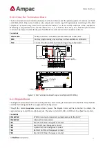
6.7.2
Remote Relay Board
In the remote version the Comms In and Out Terminal Block TB9 is cabled to the RS485 Comms terminal block TB1/1,
2, 3 on the Main Board and can be installed up to 1.2kms from the FACP.
Note:
Can be powered from the panel or an external 27 volt source.
Fit EOL Termination
Link 1 if Last Module
on Comms Bus
Address SW
SET to 1
O N
27 Volts In
(External Supply)
TB8
TB7
TB6
TB5
TB4
TB3
TB2
TB1
O/P 8
N/C
COM
N/0
O/P 7
N/C
COM
N/0
O/P 6
N/C
COM
N/0
O/P 5
N/C
COM
N/0
O/P 4
N/C
COM
N/0
O/P 3
N/C
COM
N/0
O/P 2
N/C
COM
N/0
O/P 1
N/C
COM
N/0
N/0 = Normally Open
COM = Common
N/C = Normally Closed
TB8
TB7
TB6
TB5
TB9
TB4
TB3
TB2
TB1
S W1
TB10
-
+
O/P 8
N/C
COM
N/0
O/P 7
N/C
COM
N/0
O/P 6
N/C
COM
N/0
O/P 5
N/C
COM
N/0
O/P 4
N/C
COM
N/0
O/P 3
N/C
COM
N/0
O/P 2
N/C
COM
N/0
O/P 1
N/C
COM
N/0
RS485+
RS485-
S H D
RS485 COMMS IN / OUT
Address SW
To TB3 on the Main
Card and/or Zone
Mimic Card
1 2 3 4
O N
-
+
27 Volts Out
(External Supply)
RS485+
S H D
RS485-
Figure 12: Remote 8 Way Relay Board PCB Layout
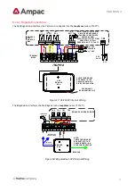
Relay Connections
Terminal/s
Function
TB1 to 8 / 1, 2, 3
N/O = Normally Open,
C = Common
N/C = Normally Closed
TB1 to 8 / 1, 2, 3
Communications Connections
Terminal
Function
1
RS485+
Communications In
2
RS485-
3
Shield
4
RS485+
Communications Out
5
RS485-
6
Shield


