


MAN1565-4
28
➢
Stage 2 outputs are switched to +24VDC. (FIRE ALARM, EVACUATE & DO NOT ENTER signs illuminated, aural
alarm sounds).
➢
The optional pre-release start delay is activated (Selected via FACP on-site programming); time out and an ON
Interlock signal will then operate the selected release circuitry.
➢
The Agent Discharge LED on the Agent Release Module and Local Control Station will illuminate when the
Pressure Switch input on the Termination Board is activated.
➢
Activate gas-fired output.
Note:
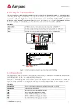
The Interlock Input can be defaulted to the on position by placing a 10K
EOL termination resistor across
the terminals TB2. 7 / 8 of the Agent Release Module and Local Control Station.
Auto Mode
Automatic discharge is when one or two zones going into alarm initiate the agent discharge sequence.
Note:
A “manual release” can still be initiated in “auto mode” but the LCS “Inhibit” control
WILL
NOT
inhibit /
abort the agent release sequence.
Single Zone Activation
,
the following discharge sequence is executed;
➢
Automatic Activation LED is illuminated on the Agent Release Module and Local Control Station.
➢
Stage 1 outputs are switched to +24VDC. (FIRE ALARM sign illuminated, aural alarm sounds).
➢
Stage 2 outputs are switched to +24VDC. (FIRE ALARM, EVACUATE & DO NOT ENTER signs illuminated, aural
alarm sounds).
➢
Optional pre-release delay is started (Selected via FACP on-site programming).
➢
The delay times out and if the Interlock signal is ON, the selected circuit will activate.
➢
The Pressure Switch field input on the Termination Board is activated and the Agent Discharge LED on the
Agent Release Module and Local Control Station will be illuminated.
➢
Activate gas-fired output.
Dual Zone Activation
,
if the first zone goes into alarm the following steps are initiated;
➢
The automatic activation LED on the Agent Release Module and Local Control Station will flash.
➢
Stage 1 outputs are switch to
–
24VDC. [FIRE ALARM sign illuminated, aural alarm sounds].
When the second zone goes into alarm, then the following steps occur;
➢
Automatic activation LED goes steady.
➢
Stage 1 outputs are switched to +24VDC. (FIRE ALARM & EVACUATE signs illuminated, aural alarm sounds)
➢
Stage 2 outputs are switched to +24VDC. (DO NOT ENTER sign illuminated)
➢
Optional pre-release delay commences (Selected via FACP on-site programming).
➢
The delay times out and if the Interlock signal is on the selected circuit will activate.
➢
The Pressure Switch field input on the Termination Board is activated and the Agent discharge LED on the
Agent Release Module and Local Control Station will be illuminated.
➢
Activate gas-fired relay output.
Service Switch
The service switch is situated on the Agent Release Module when activated causes the following;


