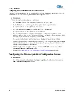
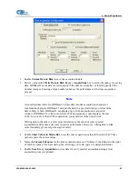
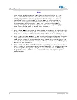
background image

4: Sample Experiments 


Taking Measurements 

There are four basic optical measurements from which to choose:  


Absorbance (see 

Absorbance Experiments


Transmission (see 

Transmission Experiments


Reflection (see 

Reflection Experiments


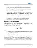
Relative irradiance (see 

Relative Irradiance Experiments

The type of measurement you take determines the configuration of the sampling optics for your system. 
Furthermore, your choice of reference and data analysis determines how the OOIBase32 presents the 
results.  

Note 

For each measurement, you must first take a reference scan and a dark spectrum scan. 
After you take a reference scan and a dark spectrum scan, you can take as many 
measurement scans as needed. However, if you change any sampling variable 
(integration time, averaging, smoothing, angle, temperature, fiber size, etc.), you must 
store new reference and dark spectrum scans.  

Application Tips  

If the signal you collect is saturating the spectrometer (intensity greater than 4000 counts), you can 
decrease the light level on scale in scope mode by: 


Decreasing the integration time 


Attenuating the light going into the spectrometer 


Using a smaller diameter fiber 


Using a neutral density filter with the correct optical density 

If the signal you collect has too little light, you can increase the light level on scale in scope mode by: 


Increasing the integration time 


Using a larger diameter fiber 


Removing any optical filters 

Absorbance Experiments  

Absorbance spectra are a measure of how much light a sample absorbs. For most samples, absorbance is 
linearly related to the concentration of the substance. OOIBase32 calculates absorbance (A

λ

) using the 

following equation: 

S

λ

 - D

λ

A

λ

 = - 

log

10


(

R

λ

 - 

D

λ


)

18


220-00000-000-02-0605


Содержание Ocean Optics QE65000

Страница 1: ... 733 2447 Fax 727 733 3962 8 a m 8 p m Mon Thu 8 a m 6 p m Fri EST Ocean Optics B V Europe Geograaf 24 6921 EW DUIVEN The Netherlands Phone 31 0 26 3190500 Fax 31 0 26 3190505 E mail Info OceanOptics com General sales inquiries Info OceanOpticsBV com European sales inquiries Orders OceanOptics com Questions about orders TechSupport OceanOptics com Technical support ...

Страница 2: ...r consent of Ocean Optics Inc in any form of binding or cover other than that in which it is published Trademarks Microsoft Windows Windows 95 Windows 98 Windows Me Windows NT Windows 2000 Windows XP and Excel are either registered trademarks or trademarks of Microsoft Corporation Limit of Liability Every effort has been made to make this manual as complete and as accurate as possible but no warra...

Страница 3: ...3 Sampling System Overview 4 How Sampling Works 4 Modular Sampling Accessories 4 Interface Options 4 Shipment Components 5 Chapter 2 Installing the QE65000 7 Overview 7 QE65000 Installation 7 Configuring the QE65000 in OOIBase32 7 Operator and Serial Number Dialog Box 8 Default Spectrometer Configuration File 8 Configure Hardware Screen 8 Spectrometer Configuration Screen 9 QE65000 Controls 10 Con...

Страница 4: ...ts 18 Transmission Experiments 20 Reflection Experiments 22 Relative Irradiance Experiments 24 Time Acquisition Experiments 26 Configuring the Time Acquisition Channel Configuration Screen 27 Configuring for a Combination of Two Time Channels 28 Configuring the Time Acquisition Configuration Screen 28 Appendix A Calibrating the Wavelength of the QE65000 31 Overview 31 About Wavelength Calibration ...

Страница 5: ...65000 Spectrometer Specifications 38 System Compatibility 39 Compatibility for Desktop or Notebook PCs 39 30 Pin Accessory Connector Pinout 39 30 Pin Accessory Connector Pinout Diagram 40 30 Pin Accessory Connector Pin Definitions and Descriptions 40 30 Pin J2 Accessory Connector Part Numbers 42 QE65000 15 Pin Accessory Cable Pinout 43 Index 45 220 00000 000 02 0605 iii ...

Страница 6: ...Table of Contents iv 220 00000 000 02 0605 ...

Страница 7: ...meter Appendix A Calibrating the Wavelength of the QE65000 Provides instructions for calibrating the QE65000 Spectrometer Appendix B Specifications Contains technical specifications and connector pinouts for the QE65000 Spectrometer Product Related Documentation You can access documentation for Ocean Optics products by visiting our website at http www oceanoptics com Select Technical Operating Ins...

Страница 8: ...ics to make a change or an upgrade to your system To facilitate these changes you must first contact Customer Support and obtain a Return Merchandise Authorization RMA number Please contact Ocean Optics for specific instructions when returning a product vi 220 00000 000 02 0605 ...

Страница 9: ...with a 2 D arrangement of pixels 1044 horizontal x 64 vertical that is responsive from 200 1100 nm The detector s columns are binned or summed inside the detector prior to the readout process thereby minimizing readout noise Additionally the detector can be cooled down to 15 ºC with the onboard TE Cooler to reduce dark noise The reduction of noise and dark signal allows integration times of the sp...

Страница 10: ...s into memory every 7 milliseconds The QE65000 operates via USB interface A 5 VDC external power supply is required for the TE Cooler TEC and to operate the spectrometer via an RS 232 interface This power supply is included with your spectrometer Features Hamamatsu S7031 1006 Detector Peak QE 90 Back thinned for good UV sensitivity MPP operation for low noise TE Cooled Spectrometer Design Symmetri...

Страница 11: ...n method requires an external power supply to power the QE65000 the HR4000 Breakout Box and a serial cable EEPROM Utilization An EEPROM memory chip in each QE65000 contains wavelength calibration coefficients linearity coefficients and a serial number unique to each individual spectrometer The OOIBase32 software application reads these values directly from the spectrometer enabling the ability to ...

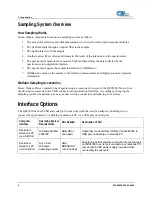
Страница 12: ...oscopic accessories for use with the QE65000 Most of our spectroscopic accessories have SMA connectors for application flexibility Accordingly changing the sampling system components is as easy as unscrewing a connector and replacing an accessory Interface Options The QE65000 has both USB and serial port connectors with the use of an adapter enabling you to connect the spectrometer to a desktop or...

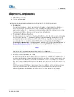
Страница 13: ... that you manually enter the calibration data in OOIBase32 select Spectrometer Configure Wavelength Calibration tab See the OOIBase32 documentation for more information refer to Product Related Documentation for instructions on accessing OOIBase32 documentation Note Please save the Wavelength Calibration Data Sheet for future reference Software and Technical Resources CD Each order ships with the ...

Страница 14: ...1 Introduction 6 220 00000 000 02 0605 ...

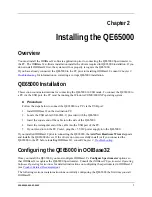
Страница 15: ... the USB cable USB CBL 1 provided with the QE65000 3 Insert the square end of the cable into the side of the QE65000 4 Insert the rectangular end of the cable into the USB port of the PC 5 If you intend to run the TE Cooler plug the 5 VDC power supply into the QE65000 If you installed OOIBase32 prior to connecting the QE65000 the Add New Hardware Wizard appears and installs the QE65000 drivers If ...

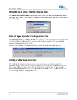
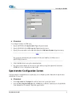
Страница 16: ...e unique serial number of the QE65000 precedes the file extension for example DEFAULT SPEC Navigate to the OOIBase32 installation directory and select the spectrometer configuration file Configure Hardware Screen The Configure Hardware screen prompts you to enter spectrometer specific information into OOIBase32 the first time you run the program Typically you need only enter this information the f...

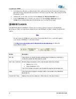
Страница 17: ...the OK button to accept the selected options 5 The spectrometer should now be able to acquire data and respond to light Exit and restart OOIBase32 to save configuration data to disk Spectrometer Configuration Screen The Spectrometer Configuration screen prompts you to configure specific channel level spectrometer information if necessary Procedure 1 Select Spectrometer Configure from the menu and ...

Страница 18: ... OOIBase32 toolbar to display the QE65000 toolbar Note If your version of OOIBase32 does not have the options listed below you should upgrade your version of OOIBase32 to the latest release Visit http www oceanoptics com technical softwaredownloads asp to obtain the latest software version Control Description TEC On Check this box to enable recommended setting for laboratory conditions or uncheck ...

Страница 19: ...perating instructions for QE65000 compatible products such as light sources sampling chambers and probes consult the Software and Technical Resources CD or the Ocean Optics website at http www oceanoptics com technical operatinginstructions asp 220 00000 000 02 0605 11 ...

Страница 20: ...2 Installing the QE65000 12 220 00000 000 02 0605 ...

Страница 21: ...s software application you may encounter installation issues that you must correct before your Ocean Optics device will operate properly Follow the applicable steps below to remove the incorrectly installed device device driver and installation files Note If these procedures do not correct your device driver problem you must obtain the Correcting Device Driver Issues document from the Ocean Optics...

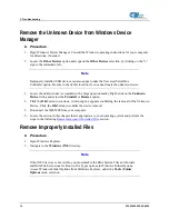
Страница 22: ... select the Uninstall or Remove option 4 Click the OK button to continue A warning box appears confirming the removal of the Unknown Device Click the OK button to confirm the device removal 5 Disconnect the QE65000 from your computer 6 Locate the section in this chapter that is appropriate to your operating system and perform the steps in the following Remove Improperly Installed Files section Rem...

Страница 23: ...he system is now able to locate and install the correct drivers for the USB device Older Version of OOIBase32 Installed If the PC to be used to interface to your QE65000 already has an older version of OOIBase32 software installed you must install the latest version of OOIBase32 You can download the latest version of OOIBase32 from the Software and Technical Resources CD or from the Ocean Optics w...

Страница 24: ...3 Troubleshooting 16 220 00000 000 02 0605 ...

Страница 25: ...re from the menu and choose the Wavelength Calibration page c For each spectrometer channel in the system enable the channel and make sure the First Coefficient Second Coefficient Third Coefficient and Intercept correspond to those of the system 5 Adjust the acquisition parameters using the Acquisition Parameters dialog bar or select Spectrum Configure Data Acquisition from the menu If you have fo...

Страница 26: ...me averaging smoothing angle temperature fiber size etc you must store new reference and dark spectrum scans Application Tips If the signal you collect is saturating the spectrometer intensity greater than 4000 counts you can decrease the light level on scale in scope mode by Decreasing the integration time Attenuating the light going into the spectrometer Using a smaller diameter fiber Using a ne...

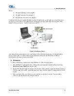
Страница 27: ...ght this is known as Beer s Law Common absorption applications include the quantification of chemical concentrations in aqueous or gaseous samples Procedure To take an absorbance measurement using OOIBase32 follow the steps below 1 Place OOIBase32 in Scope mode by clicking the scope mode icon on the toolbar or selecting Spectrum Scope Mode from the menu bar 2 Ensure that the entire signal is on sc...

Страница 28: ...r experiment After the lamp warms up again store a new reference scan You must take a dark spectrum scan before measuring absorbance 6 Put the sample in place and ensure that the light path is clear Then take an absorbance measurement by clicking on the Absorbance Mode icon on the toolbar or selecting Spectrum Absorbance Mode from the menu To permanently save the spectrum to disk click the Save ic...

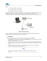
Страница 29: ...lters optical coatings and other optical elements such as lenses and fibers Procedure Perform the following steps to take a transmission measurement using OOIBase32 1 Place OOIBase32 in Scope mode by clicking the Scope Mode icon on the toolbar or by selecting Spectrum Scope Mode from the menu bar 2 Ensure that the entire signal is on scale The intensity of the reference signal should peak at about...

Страница 30: ... place and verify that the light path is clear Then take a transmission measurement by clicking the Transmission Mode icon on the toolbar or selecting Spectrum Transmission Mode from the menu bar To save the spectrum to disk click the Save icon on the toolbar or select File Save Processed from the menu bar Note If you change any sampling variable integration time averaging smoothing angle temperat...

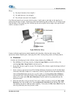
Страница 31: ...ode by clicking the Scope Mode icon on the toolbar or by selecting Spectrum Scope Mode from the menu bar 2 Ensure that the entire signal is on scale The intensity of the reference signal should peak at about 50 000 counts 3 Take a reference spectrum with the WS 1 Diffuse Reflectance Standard or the STAN SSH High reflectivity Reference Standard You must take a reference spectrum before measuring re...

Страница 32: ...of energy at each wavelength emitted from a radiant sample In relative terms it is a comparison of the fraction of energy the sample emits and the energy the sampling system collects from a lamp with a blackbody energy distribution normalized to 1 at the energy maximum OOIBase32 calculates relative irradiance with the following equation Sλ Dλ Iλ Bλ Rλ Dλ Where Bλ the relative energy of the referen...

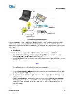
Страница 33: ...um Scope Mode from the menu bar 2 Ensure that the entire signal is on scale The intensity of the reference signal should peak at about 50 000 counts Note The light source must be a blackbody of known color temperature 3 In the Reference Color Temperature dialog box enter the color temperature of the light source in Kelvin and click the OK button 4 Take a reference spectrum using a light source wit...

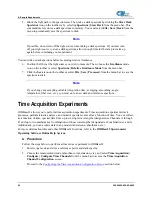
Страница 34: ...ng smoothing angle temperature fiber size etc you must store a new dark and reference spectrum Time Acquisition Experiments OOIBase32 allows you to perform time acquisition experiments Time acquisition experiments track processes perform kinetic analyses and monitor spectral events all as a function of time You can collect as a function of time spectral data from up to six single wavelengths desig...

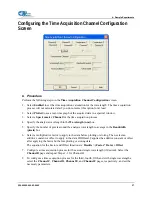
Страница 35: ...xels around the analysis wavelength to average in the Bandwidth pixels box 6 Select a multiplicative factor to apply to the data before plotting or storing Then select an additive constant or offset to apply to the data OOIBase32 applies the additive constant or offset after applying the factor but before plotting or storing data The equation for the Factor and Offset functions is Results Factor D...

Страница 36: ...toring Then select an additive constant or offset to apply to the data OOIBase32 applies the additive constant or offset after applying the factor but before plotting or storing data The equation for the Factor and Offset functions is Results Factor Data Offset 7 Configure a time acquisition process for the Combination 2 page if desired This page is virtually identical to the Combination 1 page wi...

Страница 37: ...dow If OOIBase32 collects more than 1024 acquisitions it only displays the last 1024 To store more than 1024 acquisitions you must stream the data to disk Writing data to the disk is a slow process relative to the speed of some spectral acquisitions and causes a decrease in system performance However writing data to disk more frequently gives a larger margin of safety 4 Enable Show Values in Statu...

Страница 38: ... does not begin until you start the time acquisition process Be sure to select Hours Minutes Seconds or Milliseconds immediately to the right of the initial delay entry 8 Enter a value to set the Frequency of the data collected in a time acquisition process OOIBase32 stamps data from a time acquisition with a time accurate to one millisecond Be sure to select Hours Minutes Seconds or Milliseconds ...

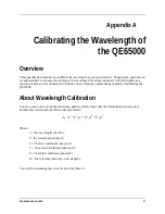
Страница 39: ...mends periodically recalibrating the QE65000 About Wavelength Calibration You are going to be solving the following equation which shows that the relationship between pixel number and wavelength is a third order polynomial λp I C1 p C2 p2 C3 p3 Where λ the wavelength of pixel p I the wavelength of pixel 0 C1 the first coefficient nm pixel C2 the second coefficient nm pixel2 C3 the third coefficien...

Страница 40: ...ting the Wavelength of the Spectrometer Procedure Perform the steps below to calibrate the wavelength of the spectrometer 1 Place OOIBase32 into Scope mode and take a spectrum of your light source Adjust the integration time or the A D conversion frequency until there are several peaks on the screen that are not off scale 2 Move the cursor to one of the peaks and position the cursor so that it is ...

Страница 41: ... 0 25 0 13 0 05 0 04 0 01 0 00 0 19 0 06 0 09 0 06 0 15 0 10 0 06 0 13 0 19 5 Use the spreadsheet or calculator to calculate the wavelength calibration coefficients In the spreadsheet program find the functions to perform linear regressions If using Quattro Pro look under Tools Advanced Math If using Excel look under Analysis ToolPak 6 Select the true wavelength as the dependent variable Y Select ...

Страница 42: ... The Welcome screen appears 5 Click the Next button The Destination Location screen appears 6 Accept the default installation location or click the Browse button to specify a directory Then click the Next button The Program Manager Group screen appears 7 Click the Next button The Start Installation screen appears 8 Click the Next button to begin the installation Once the installation finishes the ...

Страница 43: ...m of how light moves through the optical bench of a QE65000 Spectrometer The optical bench has no moving parts that can wear or break all the components are fixed in place at the time of manufacture Items with an asterisk are user specified QE65000 Spectrometer with Components See QE65000 Components Table on the following page for an explanation of the function of each numbered component in the QE...

Страница 44: ...Light enters the spectrometer passes through the SMA Connector Slit and Filter and then reflects off the Collimating Mirror onto the Grating 5 Grating Diffracts light from the Collimating Mirror and directs the diffracted light onto the Focusing Mirror Gratings are available in different groove densities allowing you to specify wavelength coverage and resolution in the spectrometer Only Ocean Opti...

Страница 45: ...option available 150nm VUV option includes purge port and window removal no TE cooling 200 925 nm with HC1 grating Active area 24 576 x 1 392mm Pixel size 24 6 µm square Pixel well depth 300K electrons each well 1 5M electrons column summing well Dark Current 4000 e pixel sec 25 ºC 200 e pixel sec 0 ºC Dark noise 2 5 RMS counts Readout noise 1 5 counts RMS 40 electrons Linearity Uncorrected Correc...

Страница 46: ...ower Supply 1 18 kg 2 6 lbs 0 45 kg 1 lb Temperature Operation Storage TE Cooler can only cool 40 C below ambient temperature 0 C to 50 C 30 C to 70 C Humidity 0 90 noncondensing Power consumption No TE Cooler With TE Cooler 500 mA 5 VDC 3 5A at 5V Supply Voltage 4 5 5 5 V Power up Time 2s depending on code size Signal to noise ratio 1000 1 single acquisition 38 220 00000 000 02 0605 ...

Страница 47: ... USB 2 0 480 Mbps USB 1 1 compatible RS 232 3 wire System Compatibility The following sections provide information on hardware and software requirements for the QE65000 Compatibility for Desktop or Notebook PCs To use the QE65000 you must have a PC that meets the following minimum requirements IBM compatible PC with Pentium or higher processor 32 MB RAM OOIBase32 Spectrometer Operating Software Wi...

Страница 48: ...ccessory Connector Pinout Diagram 30 Pin Accessory Connector Pin Definitions and Descriptions The following table contains information regarding the function of each pin in the QE65000 s 30 Pin Accessory Connector Pin Function Input Output Description 1 RS232 Rx Input RS232 receive signal Communicates with a PC over DB9 Pin 3 2 RS232 Tx Output RS232 transmit signal Communicates with a PC over DB9 ...

Страница 49: ...pecifications no TEC power 13 SPI Data Out Output SPI Master Out Slave In MOSI signal for communication to other SPI peripherals 14 VCC or 5VIN Input or Output Input power pin for QE65000 When operating via USB this pin can power other peripherals Ensure that peripherals comply with USB specifications no TEC power 15 SPI Data In Input SPI Master In Slave Out MISO signal for communication to other ...

Страница 50: ...mmable digital input output channel number 27 Ground Input Output Ground 28 GPIO 8 Input Output General purpose software programmable digital input output channel number 29 Ground Input Output Ground 30 GPIO 9 Input Output General purpose software programmable digital input output channel number 30 Pin J2 Accessory Connector Part Numbers The part numbers for the 30 pin accessory connector on the Q...

Страница 51: ...cessory Cable Pinout Pin Description Pin Description 1 Single_strobe 9 GPIO 9 2 ContStrobe 10 GND_SIGNAL 3 V5_SW 11 SDA 4 ExtTrigIn 12 SCL 5 ExtTrigIn 13 LampEnable 6 GPIO 8 14 A_IN 7 A_OUT 15 GPIO 7 8 ExtTrigIn 220 00000 000 02 0605 43 ...

Страница 52: ...B Specifications 44 220 00000 000 02 0605 ...

Страница 53: ... CCD 37 CCD Detector 36 collimating mirror 36 compatibility 39 Desktop or Notebook PCs 39 Components Table 36 Configure Hardware 8 configuring 7 D Default Spectrometer Configuration File 8 detector 37 Detector Collection Lens 36 document audience v purpose v summary v E EEPROM 3 Experiments Absorbance 18 Reflection 22 Relative Irradiance 24 Time Acquisition 26 Transmission 20 F filter 36 focusing ...

Страница 54: ...tup 7 shipment components 5 slit 36 SMA Connector 36 Software and Resources Library CD 5 specifications 35 detector 37 QE65000 37 spectrometer 38 Spectrometer Configuration Screen 9 spectroscopic accessories 11 System Requirements 3 T TE Cooler 1 2 7 10 38 Time Acquisition 26 Troubleshooting 13 U upgrades vi USB ADP PC 4 USB CBL 1 4 W Wavelength Calibration about 31 Wavelength Calibration Data Fil...

Отзывы: