MAN2285-9
Page 25
8
Interfacing
Because of the flexible nature of the FastSense 25 detector and the many possible configurations, there are
many options for interfacing the detectors to the FACP. These include many third party interfaces available
from various manufacturers. Because of this, it is not possible to give a complete list of all interfacing methods
but the following pages will give details of the most common methods that are likely to be used.
8.1
Setting the detector address
In order to identify itself to the PC Command Module or fire panel, each detector needs to have a unique
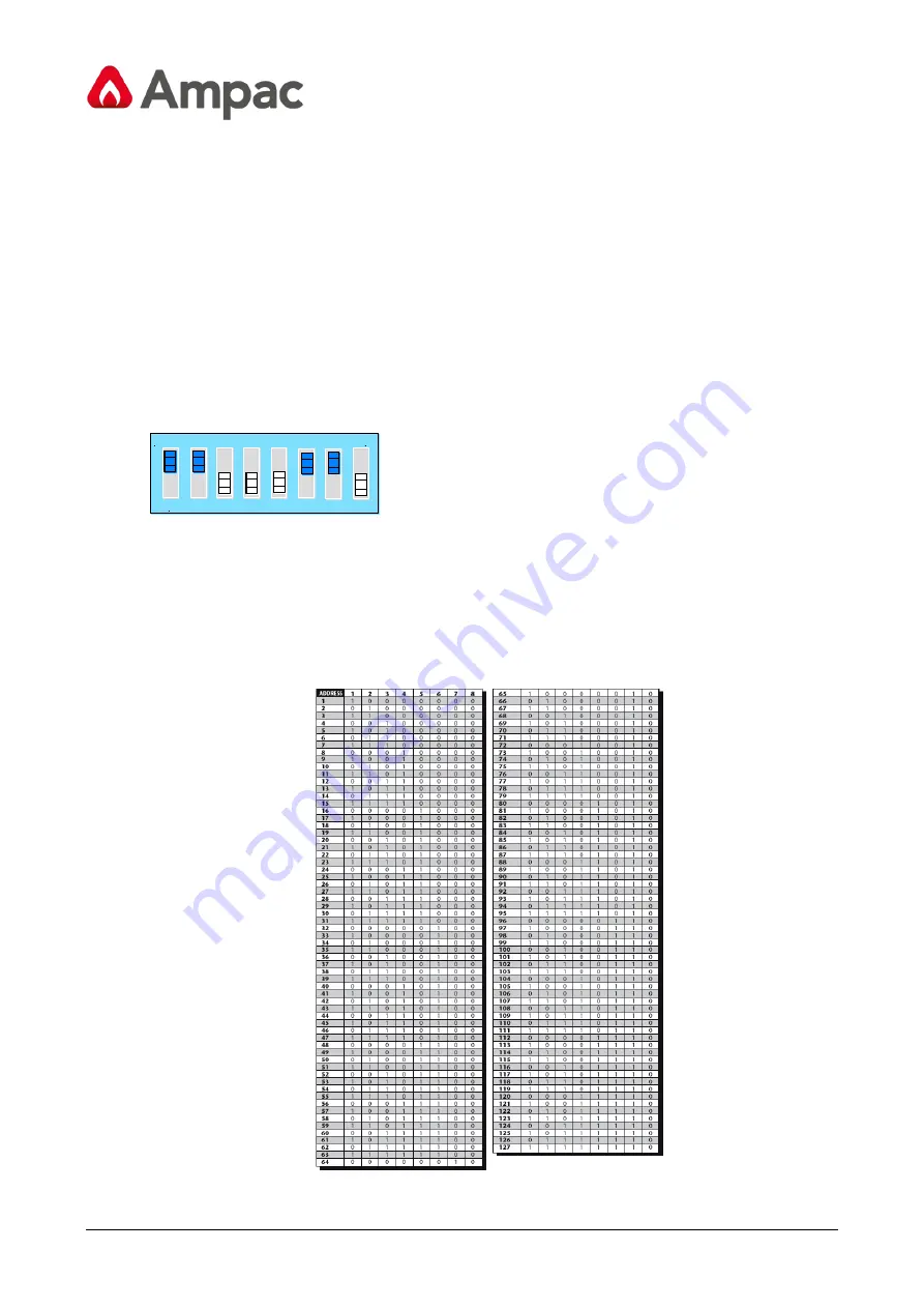
address ranging from 1 to 127. The detector address is simply set on the red DIP switch SW1 at the top left of
the opened detector on the main circuit board. The switch settings are on for 1 and off for 0, and the detector
address is set as a 7-bit binary code (switch 8 equates to a value of 128 and so is outside the usable address
range). An example is shown below.
O N
1 2 3 4 5 6 7 8
DIL
The address equates to 11000110 in binary, or (1 x 1) + (1 x 2) + (0 x 4) + (0 x 8) + (0 x 16) + (1 x 32) + (1 x
64) + (0 x 128) = 99.
The full range of available addresses and their relevant switch settings are in section 8.1.1 for reference.
8.1.1
Address table
Addresses chosen for detectors do not have to be consecutive or in a given order so long as they are all
different.


