background image

Part A: Installation procedure for all types

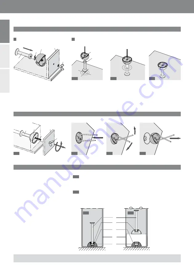
Installation using Rubber recess former

4. Installation with Steel recess former

1

 To the formwork

2

 From above into the fresh concrete

3. Removing the rubber recess former after the concrete is hardened

If installation is from above after casting the fresh concrete, the recess former 
together with the pre-assembled HALFEN DEHA Spherical head anchor is 
inserted at the specifi ed position by pushing and lightly rocking the recess 
former until its top edge is fl ush with the concrete surface. Using formwork 
lubricant, particularly in the inner of the recess former, is benefi cial when 
stripping the formwork, and to improve the lifespan of the recess former.

In those cases where the precast unit 
has to be lifted out of the mould 
without having access to the recess 
former, steel recess formers are used. 
Two fi xing versions are available:
-   for fastening with fi xing bolts 
  (steel or timber mould) and
-   for magnetic fastening to steel
  moulds, where holes cannot 
 be 

drilled. 

If this type of former is used to positi-
on the anchor horizontally within the 
formwork, provisions should be taken 
to prevent the anchor from becoming 
dislodged when pouring the concrete 
(e.g. by fi xing it to the reinforcement 
or securing it with spacers).
After removing the mould the rubber 
grommet 

 is separated from the 

cast-in HALFEN DEHA lifting anchor.

4.1

  Recess former plus spherical 


head transport anchor after 


installation, ready for 

 concreting.

4.2

  Lifting the  precast element 


from the mould.

See also instructions 

KKT-A

 for the recess formers!

 Fixing components

 Formwork

 Recess former

 Spherical head lifting anchor

 Fresh concrete

2.1

3.1

3.2

3.3

3.3

2.2

2.3

 Rubber grommet

4.1

4.2

 Auxiliary tool, i.e. reinforcement bar

2

©  2020 HALFEN · INST_KKT-E 07/15  · www.halfen.com

HALFEN KKT-E 

Assembly Instructions

Deutsch

English

Polski

Содержание DEHA

Страница 1: ... E 07 15 Assembly Instructions Montageanleitung Instrukcja montażu TR TR TR TR R R R R R R HALFEN DEHA Lifting Anchor System Inserts D HALFEN DEHA Kugelkopfanker Einbauteile GB Kotwy transportowe HALFEN DEHA z głowicą kulową PL ...

Страница 2: ...teel recess formers are used Two fixing versions are available for fastening with fixing bolts steel or timber mould and for magnetic fastening to steel moulds where holes cannot be drilled If this type of former is used to positi on the anchor horizontally within the formwork provisions should be taken to prevent the anchor from becoming dislodged when pouring the concrete e g by fixing it to the re...

Страница 3: ...400 1 1 2 2 3 4 4 4 4 The bend radius according to DIN 488 is not mandatory for the diagonal u bar Additional reinforcement in lifting anchor areas The diagonal pull reinforcement must be placed as close as possible under the recess former and installed with full contact to the anchor Reinforced area 3 times anchor length L Edge reinforcement Always insert diagonal pull reinforcement opposite to t...

Страница 4: ...in part A see also instruc tions KKT A for the recess formers Additional reinforcement must be installed the appropriate reinforcement bars dimensions see table must be arranged crosswise over the foot plate of the anchor as shown in the drawings Make sure that the reinforcement bars bear directly on the plate After the concrete of the precast element is hardened the recess former is removed see d...

Страница 5: ...y introduced The anchor should be held into position firmly during the pouring of the concrete e g by fastening to the reinforcement Some tie pins type HALFEN SPA N see Technical Product Information HALFEN Sandwich panel anchors should be arranged close to the head of the anchor acc to the drawing adjacent After concreting of the precast ele ment the recess former is removed see part A Designation ...

Страница 6: ... used with DSM recess formers code 6126 6127 and 6128 Usually the anchor is pushed into the former with an oil based lubricant Recess former type 6134 Additional rein forcement Position of the coupler tonque Lifting link Designation Length Element thickness dmin Fabric reinforce ment Additional reinforcement Allow Load central pull shear Ø ds L1 mm mm mm m mm mm 6006 2 5 0240 240 100 131 10 500 se...

Страница 7: ...eferbar für Befestigung mit Befestigungs schraube Stahl oder Holzschalung und für Magnetbefestigung an Stahl schalung wenn keine Löcher gebohrt werden können Wird der Aussparungskörper zum horizontalen Einbau eines Trans portankers verwendet sind Maßnah men erforderlich die ein Herausrut schen des Transportankers beim Rüttelvorgang verhindern z B Befesti gen des Ankers an der Schalung Fest klemmen...

Страница 8: ...3000 45 0 2 500 10 Ø14 1400 12 Ø14 1440 Ø20 2 Ø 25 80 3400 1 1 2 2 3 4 4 4 Der Biegerollendurchmesser gemäß DIN 488 muss für den Schrägzug bügel nicht eingehalten werden Einzubauende Bewehrung im Bereich der Transportanker Die Schrägzugbewehrung ist möglichst dicht am Aussparungs körper und mit Druckkontakt am Anker anzuordnen Bewehrter Bereich 3 fache Ankerlänge L Randbewehrung Schrägzugbügel imm...

Страница 9: ...Schalung eingebaut wie in Teil A dargestellt siehe auch Mon tageanleitung KKT A für die Ausspa rungskörper Als zusätzliche Bewehrung sind Be wehrungsstäbe gem nebenstehender Tabelle kreuzweise über der Platte an zuordnen siehe Bild Dabei ist darauf zu achten dass die Bewehrungsstäbe direkt auf der Platte aufliegen Nach dem Erhärten des Betons wird der Aussparungskörper entfernt siehe Beschreibung i...

Страница 10: ...er Fuß zur sicheren Lasteinlei tung in der Tragschichtmitte siehe Bild Durch Anrödeln des Kugelkopfankers an der Bewehrung wird der Anker während des Betonierens in der rich tigen Lage gehalten Im Kopfbereich des Ankers sind einige HALFEN SPA N Verbundnadeln vgl Produktinformati on Technik HALFEN Sandwichplat tenanker angeordnet siehe Bild Nach dem Erhärten des Betons wird der Aussparungskörper en...

Страница 11: ...ben muss z B Deckenherstellung im Negativ Verfahren Überkopf Pro duktion von Schachtunterteilen und Einbau in Treppenwangen Der Anker wird mit etwas Fett einfach in den DSM Aussparungskörper gesteckt Lastklasse CE Zeichen Herstellerzeichen HALFEN DEHA Lastklasse CE Zeichen Herstellerzeichen HALFEN DEHA Ankerlänge mm Lastklasse CE Zeichen Herstellerzeichen HALFEN DEHA Aussparungskörper 6134 Zulage ...

Страница 12: ...ształtki szalunkowej używa się stalowej kształtki Możliwe są dwa sposoby mocowania za pomocą śrub mocujących stalowa lub drewniana forma magnetyczne w przypadku gdy nie można wiercić otworów Jeśli taki typ kształtki szalunkowej jest użyty do umiejscowienia kotwy w poziomie należy zabezpieczyć ją przed przemieszczeniem w trakcie betonowania np przez mocowanie do zbrojenia albo zabezpieczenie rozpór...

Страница 13: ...400 12 Ø14 1440 Ø20 2 Ø 25 80 3400 1 1 2 2 3 4 4 4 Promień gięcia wg DIN 488 dla ukośnego strzemienia rozciąganego nie musi być dotrzymany Dodatkowe zbrojenie w obszarze kotwy transportowej Strzemię na siły poziome musi byćumieszczone bezpośrednio pod kształtką szalunkową i stykać się z kotwą Obszar dozbrojenia 3x długość kotwy L Zbrojenie krawędziowe Zbrojenie ukośne rozciągane zawsze umieszczać ...

Страница 14: ...EN DEHA jak pokazano na rysunkach w części A patrz również instrukcja dla kształtek szalunkowych KKT A Należy zamontować dodatkowe zbro jenie Właściwe pręty zbrojeniowe wymiary patrz tabela należy ułożyć na krzyż na płytce stalowej jak poka zano na rysunku Należy zwrócić uwa gę aby pręty zbrojeniowe leżały bez pośrednio na płytce Po związaniu betonu w prefabrykacie kształtki szalunkowe są usuwane ...

Страница 15: ...inna być zabezpieczona przed przemieszczeniem podczas betonowania np przez zamocowanie do zbrojenia W pobliżu głowicy kotwy należy rozmieścić dodatkowe kotwy typu SPA N patrz informacja techniczna HALFEN dot kotew do płyt war stwowych patrz rys obok Po związaniu betonu w prefabrykacie kształtki szalunkowe są usuwane patrz część A Nr artykułu Noś ność Min gr elementu Siatka zbrojeniowa po obu stron...

Страница 16: ...tew stosuje się kształtki szalun kowe DSM o oznaczeniu 6126 6127 i 6128 Zwykle kotwy są wciskane w kształtkę szalunkową z użyciem smaru Klasa obciążenia Znak CE Znak producenta HALFEN DEHA Klasa obciążenia Znak CE Znak producenta HALFEN DEHA Dł kotwy mm Klasa obciążenia Znak CE Znak producenta HALFEN DEHA Kształtka szalunkowa typu 6134 Dodat kowe zbrojenie Położenie języka sprzęgu uniwersalnego Sp...

Страница 17: ...17 2020 HALFEN INST_KKT E 07 15 www halfen com Deutsch English HALFEN KKT E Polski ...

Страница 18: ...18 2020 HALFEN INST_KKT E 07 15 www halfen com Deutsch English HALFEN KKT E Polski ...

Страница 19: ...fránkova 1238 1 155 00 Praha 5 Tel 420 311 690 060 Email info cz leviat com France Leviat 18 rue Goubet 75019 Paris Tel 33 1 44 52 31 00 Email info fr leviat com Germany Leviat Liebigstrasse 14 40764 Langenfeld Tel 49 2173 970 0 Email info de leviat com Italy Leviat Via F lli Bronzetti N 28 24124 Bergamo Tel 39 035 0760711 Email info it leviat com Malaysia Leviat 28 Jalan Anggerik Mokara 31 59 Kot...

Страница 20: ...Imagine Model Make Leviat com 2020 U 420 07 15 PDF 09 20 ...

Отзывы: