HAKO Scrubmaster B175 R Скачать руководство пользователя страница 41

02-7180-00.fm

41

Operation

Side panelling Fig. 11-10

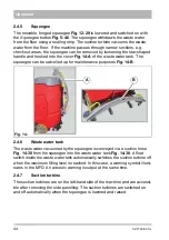
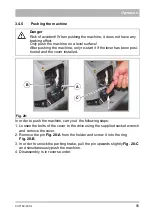
The trough batteries and the suction turbines are behind the side panelling. 
The side panelling can be easily removed using the provided wrench.

Waste water tank maintenance opening Fig. 11-32

The maintenance opening is used to drain the waste water and for cleaning 
the tank.

Fresh water filter Fig. 11-12

When supplying water from the solution tank to the brush unit, the fresh water 
is cleaned by the filter insert.

Ball cock Fig. 11-11

The ball cock is used to switch the water supply on and off manually in case 
the fresh water filter needs to be unscrewed.

Drain hose for waste water Fig. 11-31

The waste water that is collected is drained using the drain hose.

Fig. 11:

12

31

10

11

32

Содержание Scrubmaster B175 R

Страница 1: ...Scrubmaster B175 R 7180 Operating Manual Part number 88 10 3115 3922 xx Valid as from 04 2018 Cleaning Technology Municipal Technology...

Страница 2: ...rtant information for operation maintenance and care We have provided the places in this operating manual concerning your safety with a danger pictogram Your authorised Hako dealer is available at all...

Страница 3: ...by us to the usual health and safety requirements of the EC Directives see Declaration of Conformity This declaration loses its validity in the event of a modification to the machine not authorised b...

Страница 4: ...rmed by the transport company and send in the damage re port together with the consignment note to us Machine data Your machine is described clearly by the following data Please always quote these dat...

Страница 5: ...ements 24 2 2 1 Control panel 24 2 3 Multifunction display MFD 29 2 3 1 Menu guidance 29 2 3 2 Main menu 30 2 3 3 Sub menu 36 2 3 4 Controls at the machine 40 2 4 Functional description 42 2 4 1 Solut...

Страница 6: ...lug coding 76 5 3 6 Maintaining drive batteries 77 5 3 7 Taking the machine out of service for a long period 77 5 3 8 Disposing of batteries 77 5 4 Solution tank 78 5 4 1 Filling the solution tank 78...

Страница 7: ...optional 89 5 8 1 Adjusting the side brush 89 5 8 2 Changing the side brush 90 5 9 Squeegee 91 5 9 1 Cleaning the squeegee 91 5 9 2 Changing the sealing slot strip 93 5 9 3 Adjusting the sealing strip...

Страница 8: ...n of a possible danger with average risk in which death or severe physical injury can occur if it is not avoided Caution Indication of a danger with low risk in which light to medium severe physical i...

Страница 9: ...hildren should be supervised to ensure they do not play with the machine The operating manual should always be available at the machine s place of use and should therefore be stored with the machine P...

Страница 10: ...hen working with the machine pay special attention to third persons especially children When driving over thresholds raise the brush head Only use detergents suitable for automatic machines foam retar...

Страница 11: ...ntenance work and maintenance intervals specified in the operating manual must be complied with Suitable tools and protective clothing such as gloves and safety goggles must be used during cleaning an...

Страница 12: ...sed at the intended position Danger Make sure that the insulation of the battery cables is not damaged The battery cables should not rub against anything If the insulation is defective no longer use t...

Страница 13: ...under running water Damp mains plugs or mains plugs that have become wet must no longer be used Water can enter the mains plug Only qualified electricians must carry out recommissioning Check the main...

Страница 14: ...ater and detergents also see the German Water Resources Law WHG Used batteries with the recycling symbol contain reusable commodities In accordance with the symbol showing the crossed out garbage bin...

Страница 15: ...ons 1 7 Labels on the machine The following safety and instruction labels are affixed to the machine in a clearly visible and legible manner Attention Renew missing or illegible labels immediately A B...

Страница 16: ...16 01 7180 00 fm Safety instructions H Fig 2 I G I H J G J A...

Страница 17: ...dot Fig 2 C The yellow dot is located on the cover of the fresh water filter Label Type plate Fig 2 D The type plate is located in front of the left front wheel Label Explosive gases Fig 1 E The label...

Страница 18: ...erviews The description in chapter 2 contains information on the function and handling of the individual controls on the machine The controls always have the same item number in all chapters 19 2 1 10...

Страница 19: ...system cover 6 Key for side panelling 7 Holder for manual suction tool or manual spray suction tool 8 Drinks holder and storage compartment 9 Socket for USB connection 10 Side panelling 11 Ball cock...

Страница 20: ...20 02 7180 00 fm Operation 19 32 33 28 Fig 4 34 22 20 21 23 24 29 30 31 25 27 26 35 36 37 38 39 42 40...

Страница 21: ...Maintenance opening solution tank 27 Squeegee water connection 28 Fresh water drain hose 29 Squeegee 30 Suction hose 31 Drain hose waste water 32 Waste water tank maintenance opening 33 Water connecti...

Страница 22: ...43 Return button 44 Turn push knob 45 Button brush unit 46 Button squeegee 47 Button fresh water supply 48 Button boost function 49 Button on board dosing system 50 Button brush unit and squeegee 51 B...

Страница 23: ...tton I Button Reader Fleet Recorder Standard 53 Key switch 54 Button signal horn 55 Button speed reduction forwards gear 56 Button silent operation 57 Button tool operation 58 Button pre sweep suction...

Страница 24: ...The key can be pulled out Position 1 The electrical system is switched on The software version is displayed for approx 1 second on the MFD followed by the last service code for approx 3 seconds if ne...

Страница 25: ...g 5 47 The fresh water supply is switched on and off with this button Push the button Fresh water supply ON Push the button again Fresh water supply OFF Boost function button Fig 5 48 In order to remo...

Страница 26: ...is raised Squeegee button Fig 5 46 The squeegee is lowered raised and the suction turbine switched on and off with this button Push the button The squeegee is lowered and the suction turbine switched...

Страница 27: ...e brush unit the side brush unit and the squeegee are lowered and the suction turbine is switched on The brush drive and the water supply are switched on when the accelerator pedal is actuated Push th...

Страница 28: ...sh the button again Tool operation OFF Button silent operation Fig 5 56 The suction turbine is switched to silent operation with this button Push the button Silent operation ON Push the button again S...

Страница 29: ...selection Fig 6 C you are taken to the sub menu Fig 6 D 2 3 1 Menu guidance The menu is operated with the turn push knob Fig 5 44 Menus and sub menus are selected in the multifunctional display and t...

Страница 30: ...urs and minutes Changes can be made to the time in the sub menu Service alarm clock If the service alarm clock Days has elapsed this symbol is permanently visible Accelerator pedal in neutral position...

Страница 31: ...symbol Operating hours meter The operating hours in work mode are displayed The operating hours for the individual units can be called up in the sub menu Service alarm clock If the service alarm cloc...

Страница 32: ...aptive to driving speed On board dosing system On board dosing system active Brush unit Brush unit active Increased brush pressure Brush unit operating with increased brush pressure Squeegee Squeegee...

Страница 33: ...e section 5 3 1 Symbol Designation Meaning Warning symbol red spanner Faults in the functions are signalled by the red span ner A 4 digit service code is also displayed at the same time Warning symbol...

Страница 34: ...rried out using the turn push knob The following actions are possible Soft key Action window soft key Setting A Water dosing Depending on the presetting the action window appears for speed dependent o...

Страница 35: ...colour of the soft key changes from white to green F Flashlight Flashlight ON OFF by means of direct selection using the soft key If the flashlight is switched on the colour of the soft key changes fr...

Страница 36: ...the clock calen dar set in the sub menu Some sub menus require additional access rights After calling up the sub menu the cursor automatically jumps to the operating hours menu To return to the main m...

Страница 37: ...menu Fig 9 C The maintenance menu contains the following menu items The Maintenance instructions sub menu Activation deactivation of speed dependent water dosing Activation deactivation of automatic s...

Страница 38: ...er specific settings A C Definition of User specific settings A C 9 settings are available in the selection menu The specified settings 1 6 contain predefined standard procedures User specific setting...

Страница 39: ...wing actions Delete the last service information when the fault has been remedied Obtaining detailed information Deletion of the last service information from the display Select the Delete symbol with...

Страница 40: ...ously adjust the speed at the same time If the accelerator pedal is not actuated it automatically returns to the zero position and the machine stops Filling opening fresh water Fig 10 40 The solution...

Страница 41: ...is used to drain the waste water and for cleaning the tank Fresh water filter Fig 11 12 When supplying water from the solution tank to the brush unit the fresh water is cleaned by the filter insert B...

Страница 42: ...used waste water is absorbed by the squeegee and conveyed into the waste water tank A seat contact ensures that the machine can only be operated when the oper ator is sitting on the seat 2 4 1 Solutio...

Страница 43: ...shes in the rotating brush unit can be ejected for maintenance pur poses by pressing the Brush decoupler Fig 8 C soft key in the MFD see section 5 6 3 2 4 3 Side brush unit In order to brush up coarse...

Страница 44: ...wivelled up for maintenance purposes Fig 14 B 2 4 6 Waste water tank The waste water vacuumed by the squeegee is conveyed via a suction hose Fig 14 30 from the squeegee into the waste water tank Fig 1...

Страница 45: ...he machine variants are equipped with different maintenance free battery types Trough battery 36 V 320 Ah PzS wet Trough battery 36 V 280 Ah PzV maintenance free Battery management system BMS The Scru...

Страница 46: ...up the machine charge the used batteries fully and appropriately with commissioning charge Please observe the instruction manual of the charging device and the instruction manual of the battery manufa...

Страница 47: ...ig 15 D straight and firmly into the holder 5 Reinstall the cover using the available screws No Description 1 Checking the parking area for signs of leaks Cables and tanks must not show any sign of le...

Страница 48: ...lever Fig 16 A outwards Move seat forwards or backwards Release lever Fig 16 A and let the driver s seat engage Attention For reasons of safety the driver s seat is equipped with a seat con tact swit...

Страница 49: ...Adjust the tilt of the backrest by turning the handwheel Fig 17 B Adjusting the tilt of the armrests Adjust the tilt of the armrests by turning the wheel Fig 17 D The armrests can be folded up when n...

Страница 50: ...n 1 Turn on the machine 2 Activate the Fleet Recorder option 3 Use the driving direction selection button to select the driving direction 4 Select the cleaning programme 5 Actuate the accelerator peda...

Страница 51: ...he selected option deviating machine functions depending on the respective customer configu ration possible Ending operation Switch off the machine using the key switch Option Display LED Machine func...

Страница 52: ...9 C at the dosing pump until deter gent is present at the non return valve Setting the mixing ratio 1 Remove the grey cover Fig 19 D at the dosing pump 2 Set the mixing ratio according to the detergen...

Страница 53: ...detergent suitable for the degree of soil ing the squeegee remains raised for this Leave the detergent for approx 5 to 10 minutes subsequently scrub the floor again and work with a lowered squeegee No...

Страница 54: ...dibly It is no longer possible to push the machine see section 3 4 5 Overload protection In case of an overload e g excessively steep slopes the drive motor is switched off after a certain period of t...

Страница 55: ...rom the holder and screw it into the ring Fig 20 B 3 In order to unlock the parking brake pull the pin upwards slightly Fig 20 C and simultaneously push the machine 4 Disassembly is in reverse order D...

Страница 56: ...nt unauthorised use Environmental danger Observe the applicable laws and local regulations when disposing of detergents Attention Do not use a high pressure cleaner or steam cleaner to clean the machi...

Страница 57: ...lting and rolling away To do this securely lash the machine at both side Fig 21 A at the side Fig 21 B and the rear Fig 21 C with tension straps Attention When loading and subsequently transporting th...

Страница 58: ...es block the brush Inspect the brushes for for eign particles and remove them if necessary Brush not positioned correctly in the holder Actuate the brush decou pling system contact the service partner...

Страница 59: ...erval expired See maintenance plan 3 4 1 2 3 4 1 3 Driving not possible Error in the drive control Turn the machine OFF ON contact the customer ser vice if necessary 3 4 5 1 Cleaning function switches...

Страница 60: ...on 7 1 5 1 USB connection not working Connected consumer overloaded Check whether the consumer is draw ing too much power or there is a short circuit in the con nected cable Internal controller defect...

Страница 61: ...iver protection roof mm 1450 2080 Brush unit mm 900 1080 850 Squeegee mm 1100 1260 1100 Weight empty without batteries kg 450 455 440 Total weight ready for use kg 1010 1015 1100 Permissible total wei...

Страница 62: ...ine m3 h 100 200 200 100 200 Vacuum maximum mbar approx 50 Nominal voltage V 36 Nominal output max P1 W 7470 Power consumption drive motor P1 S2 120 min W 2335 Power consumption of vacuum motor P1 1 2...

Страница 63: ...ear of the driver meas ured under the customary condi tions of use according to DIN EN 60335 2 72 is dB A 68 64 68 64 Measuring uncertainty KpA dB A 1 4 1 5 1 6 1 3 Under the customary conditions of u...

Страница 64: ...ults Please always state the serial number in all enquiries and spare parts orders see section 1 7 type plate Hako system maintenance The Hako system maintenance specifies in single modules the specia...

Страница 65: ...operating hours Workshop stamp performed on at _______________ operating hours Hako system maintenance I 1750 operating hours Workshop stamp performed on at _______________ operating hours Hako system...

Страница 66: ...oller brush unit optional Weekly Clean the machine as required Clean the solution tank Check the sieve insert in the fresh water filter clean or replace if necessary Check the scrubbing performance of...

Страница 67: ...ry Check the fresh water supply replace worn parts if necessary Check the sealing strip slot strip of the squeegee turn or replace if necessary Check the deflecting bracket deflecting rollers at the s...

Страница 68: ...tors Hinge and joint locations of the brush lift system Check the optical condition of the machine corrosion and labels Trial run and function test Every 500 hours All maintenance work according to Ha...

Страница 69: ...ery is fully charged Battery capacity is displayed in steps of 10 Battery can be charged Battery capacity less than 10 Cleaning functions are switched off after 3 minutes Charge the battery Battery is...

Страница 70: ...Please observe the instruction manual of the charging device and the instruction manual of the battery manufacturer Hako assumes no liability for battery damage resulting from insufficient commission...

Страница 71: ...lisation phase starts and the symbol Charger with surrounding magnifying glass Fig 23 A is displayed The information about the type of battery which has been installed appears to the left of this Fig...

Страница 72: ...ing sym bols service code Possible cause Remedy Wrong battery or no battery Check battery Battery connector not connected Check battery connector Invalid charge characteristic Contact the customer ser...

Страница 73: ...ttery plug to the plug of the charger Fig 24 D 4 Switch on the charger 5 The progress of the charging process is displayed in the display Fig 24 E of the charger The charge control indicator in the MF...

Страница 74: ...d water Topping up with demineralised water Connect the end piece of the aquamatic system Fig 25 B to a container with demineralised water Observe sufficient gradient ensuring the water can flow into...

Страница 75: ...t the battery trough upwards and swivel out to the side Attention Only use batteries approved by Hako at the intended position The battery should only be replaced by qualified service personnel Wear s...

Страница 76: ...ust be met for the whole system Voltage coding 36 V must be identical for all plugs and bushes The colour of the coded pin in the connector housing of the machine is always yellow The colour of the co...

Страница 77: ...e for a long period If the battery is not used for more than three months the battery must be recharged 5 3 8 Disposing of batteries Used batteries with the recycling symbol contain reusable commoditi...

Страница 78: ...encing work or as required Fig 28 B Filling the solution tank with a hose 1 Place the machine on a level surface 2 Remove insert in grey cover Fig 29 A 3 Fill the solution tank up to approx 15 cm belo...

Страница 79: ...g unit 1 Fit the hose with the quick coupler Fig 31 A Do not yet open the water supply 2 Push the operating button Fig 31 B The indicator knob Fig 31 C protrudes 3 Open the water supply water starts t...

Страница 80: ...r tank via the drain 5 Ensure that the drain hose closure is fully closed after draining Fig 32 B 5 4 3 Cleaning the solution tank 1 Empty the solution tank see section 5 4 2 2 Undo the screw clamp wi...

Страница 81: ...ed off and the waste water tank should be drained immediately 1 Drive to a suitable disposal centre 2 Position the machine ensuring the drain hose Fig 33 31 reaches the drain in the ground 3 Turn off...

Страница 82: ...f the tank cap with one hand Open the tank cap until the support Fig 34 C engages 4 Clean the waste water tank thoroughly with the water hose spray nozzle Fig 34 D 5 Also flush the drain hose 6 Close...

Страница 83: ...39 daily and clean it as required 1 Rotate the locks Fig 36 A downwards and remove the intake sieve Fig 36 39 2 Thoroughly clean the intake sieve under running water 5 5 5 Checking the seal at the dra...

Страница 84: ...er sieve as required 4 Reinsert the filter sieve and filter cover and open the ball cock 5 5 7 Checking the seal in the tank cap Check the function of the seal in the tank cap Fig 39 A daily and repla...

Страница 85: ...ged when the pointer Fig 40 B is in the red zone at the latest 1 Ejecting the brushes pads see section 5 6 3 2 Inserting new brushes pads see section 5 6 4 5 6 2 Cleaning the brushes Clean the brushes...

Страница 86: ...Swivel down the wiper see section 5 10 1 and remove the brushes pads 5 6 4 Coupling the brushes pads 1 Make sure that the rotating brush unit has been raised and the machine is stationary 2 Place the...

Страница 87: ...red 1 Turn off the machine 2 Swing down the wiper on the right hand side of the machine 3 Reach into the recessed grip below the dirt hopper with one hand and remove the dirt hopper Fig 44 A 4 Empty t...

Страница 88: ...es under running water 3 Install the brushes see section 5 7 5 5 7 4 Disassembling the brushes 1 Turn off the machine 2 Swing down the wiper see section 5 10 1 3 Unlock the brush holder Fig 45 A Press...

Страница 89: ...annot be changed Readjusting the side brush position Check side brush weekly for wear In the event of wear or after changing the side brush adjust as follows 1 Place the machine on a level surface 2 L...

Страница 90: ...h unit Fig 46 59 3 Fit the side brush Fig 47 A to the hub Fig 47 B 4 Position the carrier plate Fig 47 C in such a way that the pin of the hub Fig 47 D goes through the hole of the carrier plate and t...

Страница 91: ...ine to a suitable location with drain in floor 2 Switch off machine and ensure that the squeegee is in the raised position 3 Pull off the suction hose Fig 49 D 4 Fold over the squeegee Get hold of han...

Страница 92: ...The squeegee is lowered and the suction is switched on 3 Move the machine forward a little so that the sealing lips are tilted back 4 Connect hose with 1 2 quick coupling to connection of squeegee Fi...

Страница 93: ...hose Fig 50 C 2 Loosen the star shaped handles Fig 50 D and remove the squeegee 3 Replacing the sealing strip Release the tension strap Fig 50 E and remove Replacing the slot strip Fold over the turn...

Страница 94: ...th the squeegee key Fig 52 46 2 Loosen the lock nuts Fig 51 A and turn the adjusting bushing Fig 51 B to adjust the squeegee so that the ends of the sealing strips barely have con tact with the ground...

Страница 95: ...rollers and the lower edge of the sealing strip 1 Place the machine on a level surface 2 Lower the squeegee The sealing strips must now be resting vertically onto the floor 3 Loosen nuts Fig 53 B and...

Страница 96: ...he rubber if necessary 1 Loosen the wing nut Fig 54 B 2 Remove the clamping band Fig 54 C 3 Turn the rubber of the wiper can be used 4 times or replace it Assembly is in reverse order Note During inst...

Страница 97: ...ection of the machine Fig 55 E 4 Use the tool operation button Fig 55 57 on the control panel to switch the tool on and off The operator must not be sitting on the seat Push the button twice Spray suc...

Страница 98: ...the tool into the opening of the vacuum system Fig 56 C 3 Use the tool operation button Fig 56 57 on the control panel to switch the tool on and off The operator must not be sitting on the seat Push t...

Страница 99: ...peration button Fig 57 57 on the control panel to turn the water supply on and off The operator must not be sitting on the seat Push the button Spray nozzle water supply ON Push the button again Spray...

Страница 100: ...100 06 7180 00 fm Attachments options...

Страница 101: ...of the EC Directive 2006 42 EC as well as the require ments according to 2014 30 EC The following standard s and technical specifications was were referred to for the correct implementation of the saf...

Страница 102: ......

Отзывы: