background image

31 / 48 

Hakki Pilke 55 Pro 

Translation 

Version 3-2022 


5.3.


Changing the hydraulic oil and filters 


1.


Turn  off  the  machine  and 
disconnect  it  from  its  power 
source. 


2.


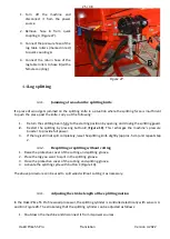
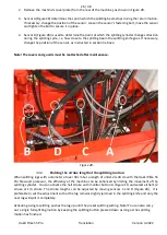
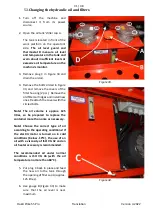
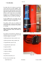
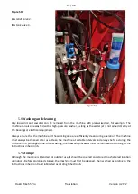
Open the oil tank’s filler cap A.


The tank is located in front of the 

work  platform  on  the  operator’s 

side. 

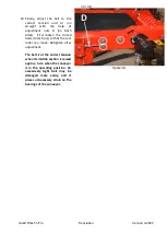
The  oil  level  guard  and 

thermostat  D  measure  oil  level 
and temperature in the tank and 
warn  about  insufficient  levels  or 
excessive oil temperature on the 

machine’s monitor.


3.


Remove  plug  C  in  Figure  34  and 
drain the old oil. 


4.


Remove the bolts circled in Figure 
33, and remove the covers of the 
filter housing (2 pcs).  Remove the 
old filter cartridges and install new 
ones. Reattach the covers with the 
circled bolts. 


Note!  The  oil  volume  is  approx.  125 
litres,  so  be  prepared  to  replace  the 
container more than once as necessary.  
 
Note!  Choose  the  correct  type  of  oil 
according to the operating conditions! If 
the  electric  motor  is  turned  on  in  cold 
conditions  (below  -10°C),  the  use  of  an 
oil with a viscosity of ISO VG 32 and an 
oil heater accessory is recommended.  
 
The  recommended  oil  under  normal 
conditions  is  ISO  VG  46  (with  the  oil 
temperature no more than 60°C).  


5.


Put plug C back in place and feed 
the  new  oil  to  the  tank  through 
the opening of filler cap A (approx. 
125 litres).  
 

6.


Use  gauge  B  (Figure  33)  to  make 
sure  that  the  oil  level  is  near 
maximum. 


Figure 33. 


Figure 34. 


Содержание 55 PRO

Страница 1: ...ssembly operation and maintenance EC Declaration of Conformity Safety instructions Guarantee terms TP Silva Oy Valimotie 1 FI 85800 Haapaj rvi tel 08 7727300 info hakkipilke fi www hakkipilke fi ENGLI...

Страница 2: ...2 Tractor drive 14 3 2 3 Electrical drive 15 3 2 4 Adjusting the log length 16 3 2 5 Using the XL Conveyor out feed conveyor accessory 17 3 2 6 Adjusting and using the splitting knife 18 3 2 7 Using...

Страница 3: ...placing the saw bar 29 5 2 Changing the oil of the multiplier gear 30 5 3 Changing the hydraulic oil and filters 31 5 4 Conveyor maintenance 32 5 4 1 Replacing and tightening the in feed conveyor belt...

Страница 4: ...estimating the diameter of the log you are about to cut note that the shape of the log and other factors such as branches and burrs make the actual diameter larger and may prevent the log from being...

Страница 5: ...ctors sufficiently tight fitting work clothing and gloves protective goggles and safety footwear Before starting up the machine the operator must ensure that the machine and its guards are intact When...

Страница 6: ...Beware of the saw chain Beware of the splitting knife Only one person may operate the machine Disconnect the power supply before any maintenance procedures The danger zone around the machine is 10 met...

Страница 7: ...machine When moving the machine make sure that the moving and lifting capacity of your tractor or forklift is sufficient for the weight of the machine Only lift the machine by the designated lifting p...

Страница 8: ...ition Always lower the machine to the ground when you stop Note Incorrect lifting may cause a hazardous situation or damage the machine Note Road transport of the machine with a tractor is prohibited...

Страница 9: ...e according to Sections 4 3 and 5 8 before arranging it for transport 3 1 1 Placing the in feed conveyor in the operating or storage position Place the in feed conveyor in the operating position as fo...

Страница 10: ...tles in the appropriate slot position the log guide plate and tighten it with the circled bolts in Figure 7 5 Also attach the other guide plate and tighten it with the four circled bolts shown in Figu...

Страница 11: ...C Control valve of the out feed conveyor accessory and multiplier knife Lever up down turns the out feed conveyor to the right left Lever right multiplier knife is lowered Lever left multiplier knife...

Страница 12: ...to the upper position last log for example I Fine tuning adjuster of the saw bar lowering speed Turning the adjuster clockwise reduces the lowering speed while turning the adjuster anticlockwise incr...

Страница 13: ...activate the measuring device adjustment See section 3 2 4 G Maintenance menu sensor statuses and other necessary maintenance related information H Settings change display language volume measurement...

Страница 14: ...ource Connect the cooler s power cable C to socket G of the 12V power source Connect input E of the 12V power source directly to the tractor s battery using a suitable fuse Please note The power requi...

Страница 15: ...to the lower three pin socket Figure 14a lower The electrically powered machine is turned on with the green button of the remote starter located in the control panel in the front of the machine Figur...

Страница 16: ...is not oversized and does not connect with limiter plate B Figure 16 guide plates or other machine components 1 Press display knob A once to activate the measurement change Figure 15 2 Turn the knob u...

Страница 17: ...turns to the left Lever backwards the conveyor turns to the right Note Always ensure that there is nothing in the way of the out feed conveyor before turning it The angle of the out feed conveyor is...

Страница 18: ...calculates the correct height for splitting knife B and the cylinder lifts lowers the knife to the correct height during sawing The splitting knife can be manually adjusted with the top buttons on th...

Страница 19: ...urning control lever A to the left as shown in Figure 17 4 When lowering the blade back to the lower position pull cord C in figure 20 to unlock the multiplier knife and raise the stopper D to the upp...

Страница 20: ...n operating manual Please read the manual before using the device Connect the sawdust blower to the machine as follows 1 Attach the sawdust blower s hose to connector F in Figure 22 2 Then observe the...

Страница 21: ...ect the output starting with a slow speed and increasing the speed from a minimum of 450 rpm to a maximum of 500 rpm b Electrical drive Connect the cable to the socket of the firewood processor start...

Страница 22: ...re that the speed of the out feed conveyor belt is suitable by adjusting it 1 Choose the log to process Note that the maximum log diameter is 55 cm The knottiness and shape of the log can increase the...

Страница 23: ...lowers the piece to the bottom of the splitting groove Figure 25 in a controlled manner The need for the guide plates depends on the thickness and length of the piece of wood that is being split A lon...

Страница 24: ...g the auxiliary device s hydraulic hoses into the quick couplings in Figure 26 The one marked in red to quick coupling B The one marked in black to quick coupling A The one marked in blue to quick cou...

Страница 25: ...g by pressing button C Figure 10 This recharges the machine s pressure booster to provide full power 3 If the log is still not split completely raise the splitting knife slightly approx 5 cm and repea...

Страница 26: ...e reattached after maintenance Figure 28 4 4 2 Halving the stroke length of the splitting motion When splitting logs with a diameter of over 30 cm but a length of under 24 40 cm with the Hakki Pilke 5...

Страница 27: ...veyor s belt and the belt s alignment can be adjusted as follows 1 Loosen fastening nut B Figure 29 2 Tighten loosen the belt with nut C in Figure 29 the same amount on both sides of the belt If the b...

Страница 28: ...good idea to keep a replacement chain on hand so that you do not need to interrupt your work to sharpen the chain 5 1 1 Replacing and tensioning the saw chain The Hakki Pilke 55 Pro firewood processo...

Страница 29: ...ing to steps 1 3 of Section 5 1 1 2 Remove the beam s fastening bolts A Figure 30 3 Remove fastening plate C Figure 31 and remove the saw bar from the groove 4 Place the new bar against gear wheel B t...

Страница 30: ...32 and drain the oil into a suitable container Note The multiplier gear s oil volume is 0 34 litres 2 Close plug C and open filler cap A Figure 32 3 Feed the new oil to the multiplier gear and close...

Страница 31: ...lter housing 2 pcs Remove the old filter cartridges and install new ones Reattach the covers with the circled bolts Note The oil volume is approx 125 litres so be prepared to replace the container mor...

Страница 32: ...le height 4 Disconnect the joint by using pliers for example to pull out wire A Figure 31 that holds the joint together 5 Remove the old belt 6 Slide the new belt under the table through opening B at...

Страница 33: ...sides First loosen the circled bolts total 6 pcs so that the rear roller can move Retighten after adjustment The belt is at the correct tension when its middle section is raised approx 5 cm when the c...

Страница 34: ...immediately once the lubricator s red light A is lit Figure 39 The grease volume can be changed The standard setting is 1 month cartridge Grease is only pumped when the machine is connected to 12 V v...

Страница 35: ...sented in the figures below 1 Grease nipples of the splitting knife height adjustment cylinder 2 pcs Figure 41 2 Right side nipples of the multiplier knife 2 pcs Figure 42 3 Left side nipples of the m...

Страница 36: ...Translation Version 3 2022 5 Grease nipples of guide plate 2 4 pcs Figure 45 6 Grease nipples of the out feed conveyor bearings 2 pcs Figure 46 7 Grease nipples of the log press 3 pcs Figure 47 Figur...

Страница 37: ...on Version 3 2022 8 Grease nipples of the wood measuring device 2 pcs Figure 48 9 Grease nipples of the log table support legs 2 pcs Figure 49 Figure 48 Figure 49 10 Grease nipples of in feed roller b...

Страница 38: ...38 48 Hakki Pilke 55 Pro Translation Version 3 2022 11 Drive roller nipple 1 pc Figure 51 12 Guard nipples 4 pcs Figure 52 Figure 51 Figure 52...

Страница 39: ...ich releases the screw for free rotation The factory setting for adjuster A Figure 53 is 2 turns towards the open position from the closed position Increase or decrease the amount as necessary accordi...

Страница 40: ...can be measured and checked in accordance with the following instructions The valves of the Hakki Pilke 55 Pro are presented in the figures below Figure 55 A is the control valve of the measuring devi...

Страница 41: ...oints is 1 4 Figure 58 G is the log press valve H is the feed stop valve if the bar is not up the timber feed is stopped I is a relief valve J is the return oil manifold K is the base plate for pressu...

Страница 42: ...e machine and the working area are sufficiently clean during operation The machine must always be cleaned after use Clean the machine at suitable intervals and always before storing the machine for a...

Страница 43: ...er Always when changing oil Number 97348 2 pcs 13921107005357 Grease nipples Lubrication According to Section 5 Lubrication oil SKF lubricator cartridge Check Replace as necessary X Cartridge 50050229...

Страница 44: ...ar is crooked 3 The saw chain is not supplied with sufficient oil 1 Sharpen or replace the saw chain 2 File the bar to make it straight 3 Increase oil feed The machine starts but none of the functions...

Страница 45: ...fault can be identified When submitting a guarantee claim the buyer must always include the type and serial number of the machine in the claim and present a receipt that includes the date of purchase...

Страница 46: ...antee period of the machine expires at the same time as the machine s guarantee The guarantee is void if the ownership of the machine is transferred to a third party during the guarantee period The gu...

Страница 47: ...and Name and address of the person who is authorised to compile the technical file Name Timo Jussila Address Valimotie 1 FI 85800 Haapaj rvi Finland The aforementioned person assures that Hakki Pilke...

Страница 48: ...48 48 Hakki Pilke 55 Pro Translation Version 3 2022...

Отзывы: