background image

- 22 - 

Display 


#Fishfinder 


High Frequency 

Depth bar 

Low Frequency 

Data bar 

Red color: It is selected to 

setup Frequency 

Содержание Smart7 Series

Страница 1: ...r position can be improved by DGPS correction However when you are communicating with other ships you may use a DGPS corrected position but they may not Make your position source known during communication The Electronic Chart Only official authorized charts and notices to mariners contain all the information needed for the safety of navigation and as always remember the user is responsible for th...

Страница 2: ...power supply immediately Never try to repair the system yourself Call for service Do not open Cabinet High voltage exists in the instrument Contact with voltage may cause possible injury or death Do not touch back side of the equipment Harmful line voltage is present on back side of the equipment Never try to touch back side while power is turned on Avoid excessive shock to display unit The LCD di...

Страница 3: ...om other heat source as it may malfunction be damaged or burn Use correct power source Operate your system within the specified power voltage An incorrect power supply may cause Maintenance Cautions For Maintenance Personnel Use the following safety precaution internal inspection Discharge capacitors High voltage may be retained in the capacitors if the high tension circuit several minutes after y...

Страница 4: ...maged due to a matching error Consult is for system information Check transducer Connection before power on Do not turn the power switch ON if the transducer is disconnected or if it is not inserted into the water If done the transducer or transmitter circuit may be damaged Always clean the transducer Since transducer performance can drop due to accumulated bottom growth keep the transducer clean ...

Страница 5: ...mation This device is only an aid to navigation It should be used in conjunction with all other navigation accuracy For safety always resolve any uncertainty before continuing navigation CAUTION The performance of LCD displays are degraded by continuous direct exposure to ultraviolet rays Locate your HD 70 SERIES Display away from direct sunlight When not in use Keep the display covered DISPLAY BR...

Страница 6: ...on the capability of the navigation source to provide accurate position information This device is only an aid to navigation It should be used in conjunction with all other navigation accuracy For safety always resolve any uncertainty before continuing navigation There is no direct relationship between the color of water areas and their depth The navigator shall always query the area for depth inf...

Страница 7: ... skin wash it off immediately in running water for 15 minutes If the liquid contacts your eyes immediately flush your eyes with running water for 15 minutes Contact a physician if any abnormal symptom is experienced INDICATION NOTICE It is important or warning notice on front of article It is only functions for the HD 70CF on front of article ...

Страница 8: ... 8 ...

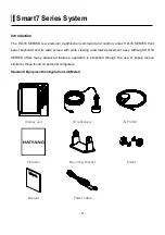
Страница 9: ... and its wide screen with wide viewing area make placement easy Although HD 70 SERIES offers many advanced features operation is simplified through the use of popup menus similar to those found on personal computers Standard Equipment Configuration List Metal Display unit Transducer GPS ANT Protector Mounting Bracket Knobs Manual Power cable ...

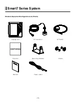
Страница 10: ... 10 Smart7 Series System Standard Equipment Configuration List Plastic Display unit Transducer GPS ANT Protector Mounting Bracket Knobs Manual Power cable ...

Страница 11: ...the depth range MENU One step Quick menu is displayed Two step Main menu is displayed GOTO Cursor display Place the cursor and press GOTO to set WPT No cursor Pointed WPT Save WPT and set free the pointed WPT No cursor No pointed WPT List for WPT route PAGE Select the configuration modification you wish Active Select the activated section WPT MOB WPT Places a WPT on the plotter main screen MOB Set...

Страница 12: ...sor to control the brightness and the contrast 3 Use day night mode Press BRT PWR shortly and change mode Use the arrow keys of the cursor to change mode Choosing the frequency on the dual Press You can see the red color is moving with the up and the down In the active frequency in the red it s on operation Choose the Gain STC Press You can see the red color is moving with the right and the left I...

Страница 13: ... 13 Smart7 Series System Metal Front Rear Main Screen Keypad Knob Mounting Bracket Connector ...

Страница 14: ... 14 Smart7 Series System Plastic Front Rear Main Screen Keypad Knob Mounting Bracket Connector ...

Страница 15: ... 15 Smart7 Series System SPEC of the connectors Metal SPEC of the connectors Plastic ...

Страница 16: ... 16 Pages Select Page Press Page key and then go to Pages screen Selectable Pages by red box and then press ENTER key red box ...

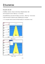
Страница 17: ...n Press PAGE key on the Pages which selected red box Refer Fig 1 1 1 as below Select the layout of the formation of screen Refer Fig 1 1 2 as below Select displays Refer Fig 1 1 3 1 1 4 as below Fig 1 1 1 Fig 1 1 2 Fig 1 1 3 Fig 1 1 4 ...

Страница 18: ...etup Customizing Data bar Edit Select the section to edit by red box Refer Fig 1 2 1 as below Press ENTER key and select the data as a user want Refer Fig 1 2 2 as below Finish the formation of data bar press CANCEL key to complete Fig 1 2 1 Fig 1 2 2 ...

Страница 19: ...Select the section to edit Refer Fig 1 3 1 as below Press ENTER key and select the data as a user want Refer Fig 1 3 2 as below Finish the formation of data bar press CANCEL key to complete If no navigation data on present activated display it is not available to edit Fig 1 3 1 Fig 1 3 2 ...

Страница 20: ... 20 Customize Screen ratio It is only available on plotter and fishfinder at the same screen MENU Screen ratio It is available to adjust the size of screen for plotter and fishfinder ...

Страница 21: ... 21 Display Chartplotter Data bar Scale Vessel icon AIS target ...

Страница 22: ... 22 Display Fishfinder High Frequency Depth bar Low Frequency Data bar Red color It is selected to setup Frequency ...

Страница 23: ... 23 Display Highway Destination waypoint name Destination waypoint Vessel XTE Alarm Radius NAV Information Direction of XTE ...

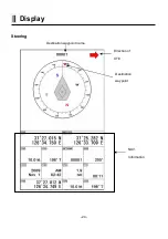
Страница 24: ... 24 Display Steering Destination waypoint name Destination waypoint NAV Information Direction of XTE ...

Страница 25: ... 25 Display GPS Information Satellite List Gain of Satellite Receiver status ...

Страница 26: ...ent position use the MOB function How to use the MOB Pressing WPT MOB key for 3 seconds and then MOB window is shown up with alarm Pressing CANCEL key for call off alarm and MOB window Pressing MOB key once again marked MOB will be disappeared on the screen MOB is not stored in the flash memory ...

Страница 27: ...while the map moves under it 3 Course Up The Course Up mode screen orientation is determined by whether or not navigation is in progress During navigation vessel present position is in the center of the Screen and the course line to the destination is straight up As your present position changes the map moves under the stationary vessel symbol If navigation is stopped the Main Screen appears as He...

Страница 28: ...fied Bottom Range from 2 5 to 20m 10 to 60ft Default setting is 10m 40ft If the depth Range is set manually the setting must place the sea bottom echo in the lower portion of the screen for Bottom Zoom to be effective 3 Bottom Lock 200KHz or 50KHz Bottom Lock divides the Fishfinder main screen image for the selected Fishfinder into two sections The left hand section displays a Normal Mode image Th...

Страница 29: ... operators to obtain information from the ship automatically requiring a minimum of involvement of ship s personnel and should have a high level of availability Connecting to the chart plotter an AIS receiver vessels with AIS transponder within VHF range are displayed on screen giving he skipper or navigator a visual interpretation of the data of nearby vessels This improves safety and specificall...

Страница 30: ...MSI Maritime Mobile Service Identity MMSI number A unique 9 digit number that is assigned to DSC radio station It primarily registers the boat information in the U S Coast Guard s national distress database for use in emergency situations Target It is a vessel equipped with AIS Information about the targets is being received by AIS Receiver and displayed on the screen Active Target Target located ...

Страница 31: ...hich wants to see It shows Information of AIS INFO window AIS INFO window 1 Name 2 MMSI number 3 National 4 Navigation Status 5 Heading 6 COG 7 SOG 8 CPA 9 TCPA 10 Latitude 11 Longitude Press ENTER key on Target which wants to see It shows Information of AIS INFO window ...

Страница 32: ... 32 Tide Information The HD 70 series contains the tide information of principal place in the world Press ENTER The icon of the tide list The window of the tide list ...

Страница 33: ... particular type The icons of the available services are shown Use the cursor key to select any facility and press ENTER The list of the ports containing the facility will be sown on the screen Then choose the port you want and press ENTER 2 2 Port by names To select the Ports by name function following the procedure Shows the list of all ports stored on the C CARD in alphabetical order and allows...

Страница 34: ...d or from the cursor position if the received fix position is not good A new window will appear in few seconds Choose the tide stations you want and press ENTER to display the tide graph page 2 5 Wrecks Searches for nearest Wrecks Use the cursor key to select the port Press ENTER to locate the selected Wreck on the map ...

Страница 35: ...ypoint 1 1 1 List Verification of saved WPT information and edit delete navigation Refer the menu from bottom list on the list window 1 1 2 Symbol size You can select the size of WPT symbol The default setting is Auto 1 2 Route Use waypoints to create a instant route for your sailing The capacity of waypoints are 20 point Every time you put waypoints on the screen the temporary route is drawn on t...

Страница 36: ...kness The size of a track is selectable between thin and pan The default setting is Thin 1 3 1 2 2 Record setup Track display interval is adjustable by distance or time The default setting is Time 1 3 1 2 3 Time interval If track interval is set in time a track displays by track time interval The track time interval and the maximum capacity is 50 000 points The default setting is 10 seconds ...

Страница 37: ... 2 2 1 Thickness The size of a track is selectable between thin and pan The default setting is Thin 1 3 2 2 2 Record setup Track display interval is adjustable by distance or time The default setting is Time 1 3 2 2 3 Time interval If track interval is set in time a track displays by track time interval The track time interval and the maximum capacity is 10 000 points The default setting is 10 sec...

Страница 38: ... Save Userdata You can save the User data in SD card 1 6 Load UserData You can load the User data from SDcard 2 Vessel offset It is possible to be set up positions of 0 1 3 and 2 3 by the standard of the center of Main Screen The Vessel offset does not work on True Motion 3 Track The Track function provides a record of the path over which your vessel has traveled A track is a series of lines conne...

Страница 39: ... 39 Chartplotter 4 Track color You can select the color of Track There are 16 sort of Track as picture 5 WPT symbol You can select shape of WPT There are 16 sort of WPT symbols as picture ...

Страница 40: ...up a previous WPT in the Present preferred route 7 2 Next WPT It is available to set up a next WPT in the Present preferred route 7 3 Route order It is available to set up the route forward and reverse in the Present preferred route 7 4 Navigation Time Setting up navigation time for TTG or ETA during navigating 7 5 Goto Type Setting up goto type for type1 or type2 ...

Страница 41: ...en 0 9 and 9 0 order To sort by Range press MENU PAGE alternate pressing of this button will toggle between nearest and furthest Pressing the or arrow keys will move the highlight blue bar over different vessels Pressing ENTER when a vessel is highlighted will display another page showing all the details so far received from this vessel Details of other vessels in the list can be accessed directly...

Страница 42: ...ce if you only wanted to view Class B vessels on the chart display then select Class B On and all the others Off 8 7 Alarm 8 7 1 CPA Alarm The CPA alarm is the closest approach alarm this allows you to set a distance when the alarm will sound if a vessel comes within that distance The default setting is OFF 8 7 2 CPA Radius The values allowed are from 0 1nm to 10nm The default setting is OFF 8 7 3...

Страница 43: ...If repeat transmissions are not received from a vessel after 7 minutes then the target is marked with a X 8 2 Remove lost vessels after If repeat transmissions are not received from a vessel after 10 minutes then the target is removed from the chart display 8 3 Vessel target It is available to setup the own vessel s AIS target display on the screen The default setting is On 8 9 Labels on vessels T...

Страница 44: ...If the Status shows Test then no further action is required as it is just a test transmission If the Status shows Active it will also show the MMSI Name and position the SART icon should now be displayed on your chart screen at that location Monitor your VHF radio on Channel 16 and establish whether any other station has received this SART message if not take the appropriate action 8 12 Fishing ne...

Страница 45: ... 45 Chartplotter 9 Calendar It is available to check the solar moon calendar and tide 0 Advance Load the additional advanced menu on the Menu ...

Страница 46: ... UserData Display Setting up shown hide the user data on the display 1 3 INFO Display Setting up shown hide common item between the HY MAP and the C MAP on the display 1 4 Map scale Setting up the map scale on the display 1 5 Palette It is possible to the palette used to enhance the visibility of the screen depending on the surround light condition The possible choices are listed in the table belo...

Страница 47: ...he chart at latitude The error can be modified in the chart latitude modification 1 7 LOT Modification Though GPS information is accurate there could be an error in the chart at longitude The error can be modified in the chart longitude modification 1 7 Map Select the chart among HY MAP C MAP and External map 1 8 1 HY Map Only for HY MAP mode 1 8 1 2M Setting up 2m of the depth line on the HY MAP ...

Страница 48: ...hown 1 8 1 8 EEZ Setting up the EEZ line on the HY MAP 1 8 1 9 Screen Magnification Setting up the Screen Magnification on the HY MAP MAX Magnification ON 0 05nm OFF 0 2nm 1 8 2 C Map Only for C MAP mode 1 8 2 1 SAT Image Setting up the overlay Satellite Image on the C MAP The default setting is shown 1 8 2 2 Font Symbols On charts it is possible to set the size of all names and symbols drawn on t...

Страница 49: ...ting is on 1 8 2 4 Perspective View Chart data may be projected in perspective mode during navigation This function allows setting the panoramic View of the chart As the upper side of the map is more compressed than the lower side a wider map area is visible The perspective view allows showing more chart information immediately ahead and around the cursor The default setting is off 1 8 2 5 Chart B...

Страница 50: ...ting is 9 2 2 Heading Line The length of the heading line is adjustable from 50 until 300 The bigger number the longer line The heading line is used in modes of the true motion and the north up The default setting is 270 2 3 Vessel Style Circle Arrow Vessel Select the vessel symbol among Circle Arrow and vessel The default setting is circle 2 4 Orient Resolution Sets you preferred Rolling Road Sca...

Страница 51: ...ext waypoint automatically The default setting is 0 05nm 3 1 3 XTE Alarm If you are out of the course it gives you a notice with alarm The default setting is OFF 3 1 4 XTE Radius It is to adjust the range of the off course The default setting is 0 25nm 3 2 Anchor 3 2 1 Anchor Alarm It is necessary when your vessel anchors The default setting is OFF 3 2 2 Anchor Radius If you vessel is out of the r...

Страница 52: ...F 3 3 2 Interval Time The time is available from one minute until sixty minutes The default setting is 3 min 3 4 User Line 3 4 1 User Line Alarm It alarms if it breaks into the setting area The default setting is OFF 3 4 2 User Line Radius It sets the range of the course alarm The default setting is 0 05nm ...

Страница 53: ...u turn up the shift the range of Fish finder shall go up from the shift range For example if you raise 5m of shift at 20m range the surface shall start 5m and the bottom range shall be 25m The default setting is 0m 4 Mode Fish finder modes are selectable for single frequency or dual and some functions 5 Zoom Range Select the range of the bottom zoom or lock It is necessary to modify the bottom The...

Страница 54: ... to level 2 The bigger number the more rejection The default setting is OFF 9 Noise Rejection Your Fish finder could be disturbed by the engine noise This function can reject the noise from the engine or other machinery instruments The default setting is OFF 10 Calendar It is available to check the solar moon calendar and tide 11 Advance Load the additional advanced menu on the Menu ...

Страница 55: ...speed of Fish finder image from 4X until 1 32X The default setting is 1X 1 3 White Line It is necessary to research a detailed fish on the bottom or a seaweed under the sea The color of the bottom changes into white or black to see the bottom easier than red The default setting is OFF 1 4 Depth On Off the depth range on the screen The default setting is ON 1 5 Depth Font Select the depth range fon...

Страница 56: ...evel is higher the color of the bar is deleted one by one 2 3 Screen Color Select he back ground color of the Fish finder for your convenience 3 Pulse Select the pulse of the output from the transducer Levels are among Low Medium and High which depends upon the depth Low is proper to research precise a fish school but it is not suitable to measure a deep depth High is opposite from Low The default...

Страница 57: ...der The default setting is OFF 5 3 2 F S depth If the alram is on It is available to setup the depth of the Fish school The default setting is 10m 5 3 3 F S Range If the the alram is on It is available to setup the Range hight of the Fish school The bar next of display is shown The default setting is 50m 5 3 4 Alarm interval If the the alram is on It is available to setup the alarm interavl The de...

Страница 58: ... 0 10 0 10 10 F The default setting is 0 7 Image Filtering This function is reduction of the noise The default setting is OFF 8 Speed Source Switch the Sensor NMEA InsideSensor Use the built in speed meter for sensor NMEA Use the external input value for NMEA The default setting is NEMA ...

Страница 59: ...ellites If it is on the latitude modify in the latitude modification 1 4 LOT Modification There could be a receiving signal error from satellites If it is on the longitude modify in the longitude modification 1 5 POG filter Step 1 OFF 59 MAX the POG Filter When it is On over step 1 you can filter the POG of the vessel to optimize it The default setting is incorrect every the country 1 6 COG filter...

Страница 60: ...lter the SOG of the vessel to optimize it The default setting is incorrect every the country 1 8 LAT LON Unit It is to select the number of the unit for Lat Lon The default setting is 4 unit 1 9 Receiving Port It is to select Inter receiver Internal External and AIS The default setting is Internal ...

Страница 61: ...elect desired unit of measure for depth of water Choose from meter M foot ft fathom fm Italian Fathom Ifm Japanese fathom Jfm cf 1m 3 281ft 0 549fm 0 609lfm 0 660jfm The default setting is Meter 2 1 3 TEMP Select desired unit of measure for temperature of water Choose from Celsius or Fahrenheit cf 1 32 2 2 Compass 2 2 1 BRG There is a difference degree where you are in the earth This function is t...

Страница 62: ... The default setting is 12 hour 2 3 3 Date Format Sets you preferred date among YY MM DD MM DD YY or DD MM YY The default setting is YY MM DD 2 3 4 Month format Sets you preferred date between Character or Number 2 3 5 Calendar setup 2 3 5 1 Week starts on You can select the first day of week The default setting is SUN 2 3 5 2 Color Saturday You can setup the color of Saturday 2 3 5 3 Color Sunday...

Страница 63: ... OFF GPRMC Recommended Minimum Specific GPS TRANSIT DATA OFF GPAPB Heading track controller Autopilot sentence B ON GPXTE Cross track error measured OFF GPBOD Bearing origin to destination OFF GPBWC Bearing and distance to waypoint ON SYPLT Samyoung autopilot OFF 2 4 2 Transmit Available to adjust transmit speed of input output in each ports 2 4 3 Buzzer It is can be buzzer on off The default sett...

Страница 64: ... and modifiable the data bar by user Fix mode It is fixed data bar by default It is not available selectable and modifiable the data bar by user The default is User mode 2 4 5 2 Navigation Data 2 4 5 2 1 Type It is a select the navigation data type The default setting is Type1 2 4 5 2 2 Edit It customizes the Navigation data section except activated the echo sounder section 2 4 5 3 Page mode It is...

Страница 65: ...s necessary for maintenance and upgrade 3 3 MAP VER It contains the version of the chart the datum and the number which is necessary for maintenance and upgrade 3 4 Simulator It is necessary for an indoor demonstration The simulations of GPS Fish finder or AIS in the memory 3 5 Language Select the language 3 6 Initialization 3 6 1 Setup Initialization reset without deleting user data 3 6 1 Factory...

Страница 66: ...ording in SD card Recording time is different by the size of the memory card 4 2 Recording List Available to display and delete the recording file 4 3 Screen capture This is the function of save the current screen Note The capture file is stored in external SD card The storage location is E9 Capture in SD card Recording time is different by the size of the memory card 4 4 Capture List Available to...

Страница 67: ...rt Datum Wreck in over 200m or depth unknown which is not considered dangerous to surface navigation Marine farm Lighthouse Wreck depth unknown which is considered dangerous to surface navigation Military restricted area into which entry is prohibited Radar transponder beacons Yacht harbor Marina Fishing prohibited Lighted offshore platform Conical buoy nun buoy ogival buoy Oil tanks Can buoy cyli...

Страница 68: ... 68 Pillar buoy Barrel buoy tun buoy Spar buoy spindle buoy Superbuoy Superbuoys are very large buoys Tides Port information ...

Страница 69: ...direct sunlight on the viewing window Also consider access to the rear panel of the unit for connecting power and cables to the various remote sensors The mounting surface must be flat and solid to support the unit and prevent vibration There should be access to the inside of the surface to permit through bolt fastening for the mounting bracket Display Unit Installation Temporarily install the mou...

Страница 70: ...nector on the rear panel of the display unit Route the power cable from the HD 70 SERIES location to the ship s power distribution panel Connect the black wire to a battery negative terminal of the power panel Connect the white wire to a fused battery positive terminal of the power panel 12 to 24 Vdc nominal If a fused terminal is not available install an in line fuse holder Care and Cleaning HD 7...

Страница 71: ...he time of printing Please refer to the appropriate NMEA specifications for details and the latest information The data sentences used by the HGP 660 are as follows Output sentences Descriptions Contents of data field GPGGA Global Positioning System Fix Data GPGLL Geographic Position Latitude Longitude GPGSA GPS DOP and active satellites GPGSV GPS Satellites in View GPVTG Course and Ground Speed G...

Страница 72: ...h provides suitably equipped users with accurat e position velocity and time data Originally the GPS developed by the U S Department of Def ense was conceived for military purposes but now it is used in a host of civilian applications GPS navigation uses satellite signals to determine your position in relation to a set of satellite o rbiting the earth The GPS constellation of satellites continuous...

Страница 73: ... that orbit the earth Signals are required from 3 satellites for two dimensional 2D position calculation whilst 4 satellites are required for three dimensional 3D position calculation As mentioned earlier GPS satellites are not geostationary but they are orbiting the earth as illu strated on the following figure The GPS constellation Note that position is repeatedly fixed through the following thr...

Страница 74: ...y accurate distances to the satellites using the Spread Spectrum Modulation method Excellence in GPS s position fixing accuracy i s mainly due to this technology 3 When the satellite locations and their distances are known the GPS receiver fixes its own p osition by triangulation The GPS position calculation As illustrated in the previous figure the position is calculated as the meeting point of t...

Страница 75: ...on the contrary accuracy is reduced when the satellites have gathered in a narrow space In the follow ing figure in both cases it is possible to obtain the GPS fix but in the left case the accuracy will be higher than the right HDOP The index for position fixing accuracy is called HDOP Horizontal Dilution Of Precision T he smaller the HDop value the more accurately the position can be fixed ...

Страница 76: ...ing power would be weaker Please follow the instruction for your installation 1 Keep from a metal 2 Over 4m away from a MF HF ANT VHF or HF whip ANT 3 Over 1 5m upper away from MF HF ANT 4 Over 1m away from a receiving ANT 5 Don t put the GPS ANT into the range of radar s beam Range 30 40 6 Over 1m away from the scanner of the radar 7 Over 5m away from the ANT of the inmarsat 8 Over 3m away form t...

Страница 77: ... 77 GPS Warning Not less than 0 5m away from the metal surface If the environment can t be satisfied from 1 to 10 have NO 10 satisfied and consider the others ...

Страница 78: ...ct sunlight on the viewing window Also consider access to the rear panel of the unit for connecting power and cables to the various remote sensors The mounting surface must be flat and solid to support the unit and prevent vibration There should be access to the inside of the surface to permit through bolt fastening for the mounting bracket Display Unit Installation Temporarily install the mountin...

Страница 79: ...during the rest of the installation process Power Connection Power is supplied to the Fishfinder Unit through a connector on the rear panel of the display unit Route the power cable from the Fishfinder Unit location to the ship s power distribution panel Connect the black wire to a battery negative terminal of the power panel Connect the white wire to a fused battery positive terminal of the power...

Страница 80: ...nd for different beam angels and sonar frequencies Several different transducers may be used with the HD 70 SERIES Refer to the optional Equipment list for the variations available CAUTION Mounting a sonar transducer for your HD 70 SERIES Sonar requires drilling holes into the hull of your boat which could affect its water integrity Therefore installation should be attempted only by qualified indi...

Страница 81: ...g should be about 1 8 inch below the leading edge The adjustable stainless steel bracket is designed to allow fine tuning of the transducer position once the installation is completed Route the transducer cable as far as possible away from the boat s power cables engine controls and other electrical cables Do not route transducer cables near your VHF radio power or antenna cables Assemble the tran...

Страница 82: ...dy bronze construction assures a secure installation and provides a strong base for fairing blocks if needed to compensate for hull shape The transducer should be installed in a location free of bubbles and away from disturbed water flow Smooth water flow around the transducer and along its surface is very important for consistent operation Areas in the center third of water line length at cruisin...

Страница 83: ...ten In this situation install fairing blocks both inside and outside the hull Install the transducer with the face aiming straight down To prevent leakage any gaps between the stem threads and holes drilled in the hull should be completely filled with waterproof marine ...

Страница 84: ... 84 Installation sealant Tighten the stem nuts securely but do not over tighten Water Line Drifting Water Line Cruising Best Location Stem Marine Sealant Hull Fixing Nut ...

Страница 85: ...nt sea growth effects the face of the transducer may be coated with antifouling paint specially formulated for transducers Do not use regular antifouling paint on the face of the transducer The bronze housing may be coated with any antifouling paint If fairing blocks are used especially if made of wood complete sealing prior to painting is important Marine Sealant Stem Fixing Outer Fairing Block H...

Страница 86: ... 86 ...
Страница 87: ...O DES BY NONE SCALE PER N MODEL CHK BY MATERIAL DRA BY Y S KIM OLIX CO LTD DATE 05 07 2012 HD 70 Series Y S KIM Power Cable S7 DC10303M Y S KIM Y S KIM To HD 70 series J1 16 03P Red Black NOTE 2 1 3 2 1 BLACK RED DC 12 40V ...

Страница 88: ...N MODEL CHK BY MATERIAL DRA BY Y S KIM OLIX CO LTD DATE 05 07 2012 HD 70 Series HFF 650 Y S KIM Data Cable S7 DC10103M Y S KIM Y S KIM To HD 70 series J2 J3 16 06P Shrinking Tube 20 Shrinking Tube 15 00 7 00 3 00 cut Cable 1 6 5 3 4 2 1 6 5 3 4 2 ...

Страница 89: ...1 2 12 36 FUNCTION PIN WIRE COLOR Power Calbe 2 4 3 5 7 6 8 1 Kim Y S Kim Y S Kim Y S DRA BY Park D J HD 70 Series CHK BY PER N DES BY MODEL MATERIAL SCALE 1 2 2012 05 07 DATE OLIX CO LTD S7 DC10301P DESCRIPTION DWG NO Power Cable I O ...

Страница 90: ... 90 KIM Y S KIM Y S KIM Y S D J PARK S7 PA90101 HD 70 series DESCRIPTION DWG NO DES BY 1 1 SCALE PER N MODEL CHK BY MATERIAL DRA BY GPS ANT OLIX CO LTD DATE 2012 05 07 ...

Страница 91: ...3 TD1 4 TD_GND 5 TD2 6 TEMP_VCC 7 TEMP_SIG 8 SPD_GND To SMART7 TD Connector S7 TD90201M Kim Y S Kim Y S Kim Y S DRA BY Park D J CHK BY PER N DES BY 2013 04 08 DATE DWG NO DESCRIPTION NONE SCALE MATERIAL MODEL SMART7 mark option OLIX CO LTD ...

Страница 92: ...E 2 SPD_VCC 3 TD1 4 TD_GND 5 TD2 6 TEMP_VCC 7 TEMP_SIG 8 SPD_GND To SMART7 TD Connector S7 TD90201P Kim Y S Kim Y S Kim Y S DRA BY Park D J CHK BY PER N DES BY 2013 04 08 DATE DWG NO DESCRIPTION NONE SCALE MATERIAL MODEL SMART7 mark option ...

Страница 93: ... 93 PLAN DIMENSIONS 2012 02 16 DATE OLIX CO LTD DRA BY MATERIAL CHK BY MODEL PER N SCALE NS DES BY DWG NO DESCRIPTION HD 70C METAL S7 PL00DM Park D J Kim Y S Kim Y S Kim Y S ...

Страница 94: ...4 Kim Y S Kim Y S Kim Y S Park D J S7 PL00DP HD 70 Series DESCRIPTION DWG NO DES BY NS SCALE PER N MODEL CHK BY MATERIAL DRA BY OLIX CO LTD DATE 2012 02 16 PLAN DIMENSIONS 6 2 5 4 3 7 8 1 1 8 7 3 4 5 2 6 ...

Страница 95: ...r a user purchases the product within one 1 year 2 Accessories One 1 year for consumed accessories including TD after a user purchases them Service in Charge 1 Over the term from the guarantee 2 Damage from user s carelessness inundation impact 3 Intentional dismantle modification or remodeling of the unit 4 Unauthorized parts components or accessories are used in the unit 5 Installed or maintaine...

Отзывы: