


– 37 –
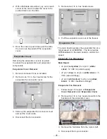
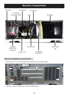
Compressor
The refrigerator uses a single speed reciprocating
compressor.
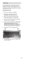
Compressor Removal
1. Remove the machine compartment cover.
2. Disconnect the compressor electricals (relay/
overload and capacitor).
3. Follow recovery procedure (see
Evacuation
and Charging Procedure
under the
Replacing Sealed System Components
section of this service guide), and disconnect
the suction and discharge lines.
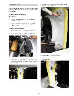
4.
8VH D ÀDW EODGH VFUHZGULYHU WR UHPRYH WKH
four locking clips on the compressor posts.
5.
/LIW WKH FRPSUHVVRU Rႇ WKH SRVWV DQG RXW RI
the machine compartment.
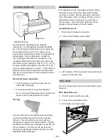
Drier
7KH GULHU LV XVH WR ¿OWHU PRLVWXUH DQG SDUWLFXODWHV
which may be present out of the sealed system.
Any time the sealed system is accessed or
repaired, the drier should be replaced.
Drier Removal
1. Remove the machine compartment cover.
2. Follow recovery procedure (see
Evacuation
and Charging Procedure
under the
Replacing Sealed System Components
section of this service guide), and cut or
unbraze the tubing from the drier. If cutting
the capillary tube, make sure to take care not
to pinch the capillary tube shut.
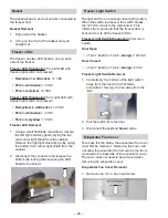
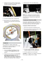
Compressor Diagnosing
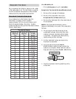
Check the resistance of the compressor windings.
S to C
: ~6 ohms
R to C
: ~4 ohms
If the resistance is not correct or a winding is
open or shorted to the case of the compressor,
replace the compressor.
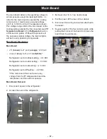
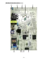
Main Board
J8 (
black
) to J10 (
green
): 120 VAC
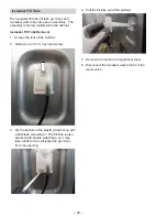
Overload/Relay Wiring
Orange
to
black
: 120 VAC
NOTE
: If voltage is present to the overload/relay,
verify that the overload and relay are good prior
to replacing the compressor.
Compressor Electricals Diagnosing
Main Board
J8 (
black
) to J10 (
green
): 120 VAC *When
compressor should be running.
Overload/Relay Wiring
Orange
to
black
: 120 VAC
Содержание GE ABE21D
Страница 1: ...GBE21D ABE21D 2016 Artistry GE Swing Door Refrigerators Technical Service Guide March 2018 31 9285 ...
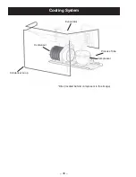
Страница 11: ... 11 LUÀRZ ...
Страница 33: ... 33 Main Board Connector Locations J10 J8 J11 J13 J4 J3 J1 J2 J7 J9 ...
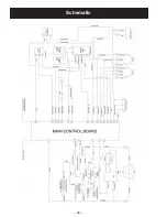
Страница 40: ... 40 Schematic ...