


– 29 –
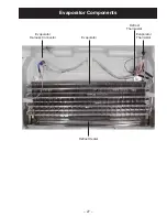
Evaporator Thermistor
The evaporator thermistor is clipped to the outlet
of the evaporator coil. The thermistor is used to
monitor evaporator temperature and terminate
defrost when the thermistor reaches 55°F.
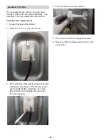
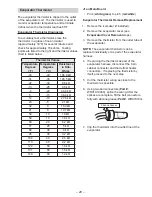
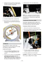
Evaporator Thermistor Diagnosing
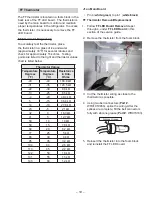
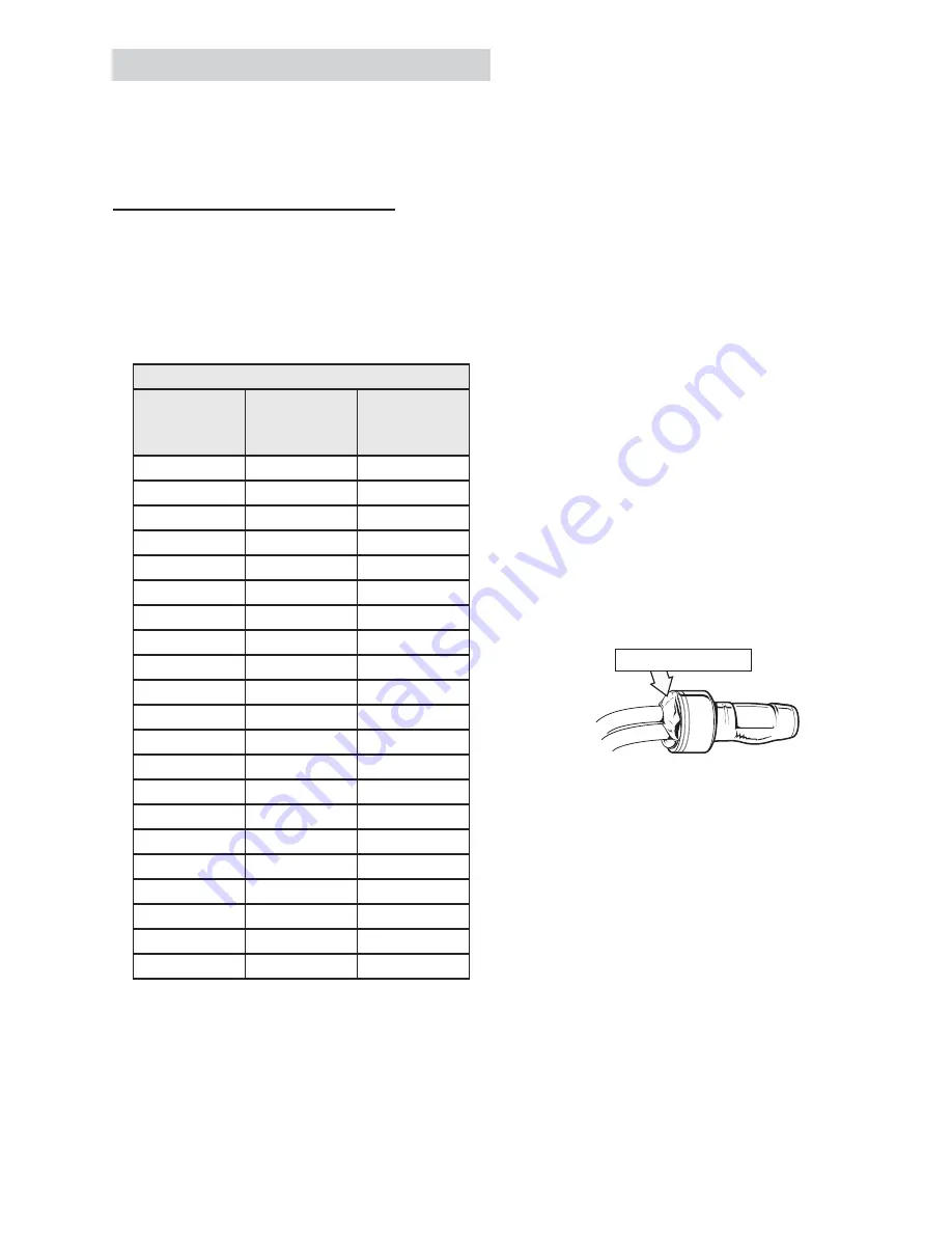
To accurately test a thermistor, place the
thermistor in a glass of ice and water
(approximately 33°F) for several minutes and
check for approximately 16k ohms. Testing
points are listed to the right and thermistor values
chart is listed below.
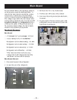
J1 on Main Board
:
Pin 4 (
white
/
green
) to pin 5 (
red
/
white
)
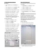
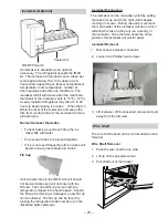
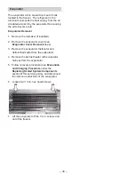
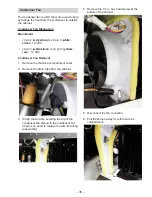
Evaporator Thermistor Removal/Replacement
1. Remove the icemaker (if installed).
2. Remove the evaporator cover (see
Evaporator Cover Removal
steps).
3. Remove the thermistor from the outlet tube of
the evaporator.
NOTE:
The evaporator thermistor can be
replaced individually or as part of the evaporator
harness.
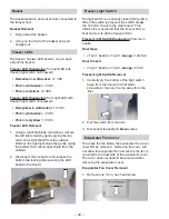
4. If replacing the thermistor as part of the
evaporator harness, disconnect the 6 pin
cabinet connector and the defrost heater
connectors. If replacing the thermistor by
itself, proceed to the next step.
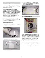
5. Cut the thermistor wiring as close to the
thermistor as possible.
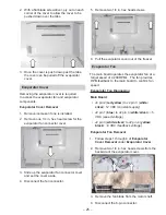
6. Using two bell connectors (
Part #
:
WR01X10466), splice the wiring. After the
VSOLFHV DUH FRPSOHWH ¿OO WKH EHOO FRQQHFWRUV
fully with silicone grease (
Part #
: WR97X163).
7. Clip the thermistor into the outlet line of the
evaporator.
Silicone Grease
Thermistor Values
Temperature
Degrees
(
°
F)
Temperature
Degrees
(
°
C)
Resistance
in Kilo-
Ohms
-40
-40
Nȍ
-31
-35
Nȍ
-22
-30
Nȍ
-13
-25
Nȍ
-4
-20
Nȍ
5
-15
Nȍ
14
-10
Nȍ
23
-5
Nȍ
32
0
Nȍ
41
5
Nȍ
50
10
Nȍ
59
15
Nȍ
68
20
Nȍ
77
25
Nȍ
86
30
Nȍ
95
35
Nȍ
104
40
Nȍ
113
45
Nȍ
122
50
Nȍ
131
55
Nȍ
140
60
Nȍ
Содержание GE ABE21D
Страница 1: ...GBE21D ABE21D 2016 Artistry GE Swing Door Refrigerators Technical Service Guide March 2018 31 9285 ...
Страница 11: ... 11 LUÀRZ ...
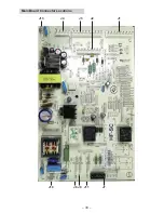
Страница 33: ... 33 Main Board Connector Locations J10 J8 J11 J13 J4 J3 J1 J2 J7 J9 ...
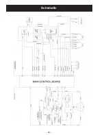
Страница 40: ... 40 Schematic ...