background image

21

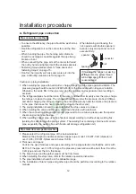
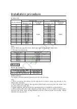
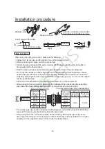
Electric wiring and the application

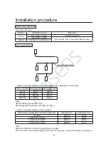
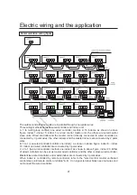
Communication wiring fi gure

The outdoor and all indoor units are in parallel through 2 non-polar wires.
Three wiring methods between wired controller and indoor unit:
A. 1 to multi (group control): one wired controller controls 2~16 indoors, as shown in above
figure, indoor 1~indoor 5: indoor 5 is wired control master unit, the others are wired control
slave units. Wired controller and the master indoor (directly connected to wired controller) is
connected by 3 polar wires; the other indoors and the master indoors are connected by 2 polar
wires.
B. 1 to 1 (one wired controller controls one indoor):  as shown in above 

fi

 gure, indoor 6~ indoor

19, indoor and wired controller are connected by 3 polar wires.
C. 2 to 1 (two wired controller controls one indoor): as shown in above 

fi

 gure, indoor 20. Either

of wired controllers can be set as master wired controller, and the other is slave wired controller.
Master/slave wired controller, and master/indoor are connected by 3 polar wires.
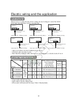
When indoor is controlled by remote controller, refer to the "wired control master unit/wired
control slave unit/remote control unit table".A, B, C on signal terminal block need not wires and
not connect the wired controller.

Содержание AV08NMSETA

Страница 1: ...Installation Manual for Outdoor Unit AV08NMSETA AV10NMSETA AV12NMSETA No 0150512770 Please read this manual carefully before using Keep this operation manual for future reference ...

Страница 2: ... the below conditions CONTENT Safety 1 Installation instruction 3 Installation procedure 6 Electric wiring and the application 21 Failure code 25 Trial operation and the performance 30 MRV S adopts simultaneous control type all indoors should be heating or cooling simultaneously To protect compressor before startup the unit should be electrified for over 12 hours If the unit is not used for a long...

Страница 3: ...or fire When installing or moving the unit the refrigerant system should be vacuumed and recharged with R 410A refrigerant If any other gas enters the system it may lead to abnormal high pressure which may cause damage or injury Please use the proper manifolds or branches during the system installation The wrong parts may cause refrigerant leakage Keep the drain pipe away from toxic gas vents to p...

Страница 4: ...he wrench to fasten the nut and flare at proper torque Excessive torque may cause flared section to broke leading to refrigerant leakage After refrigerant pipe installation please take nitrogen leakage test to avoid refrigerant leakage R 410A is the only permitted refrigerant To avoid mischarging wrong refrigerant the check valve diameter is changed for R 410A To strengthen the pipe the flared pip...

Страница 5: ... weighed by the standard balance Is there refrigerant leakage Is all the indoor power supplies can be on off simultaneously Is the power voltage in compliance with the data marked on the rating label Is the address of indoors has been set 1 Before installation 1 Before installation check if the model power supply pipe wires and parts purchased respectively are correct 2 Check if the indoors and ou...

Страница 6: ...ot be installed at the below places or it will cause damage The place where there is corrosive gas spa area etc The place blowing salty air seaside etc Exsits the strong coal smoke The place with high humidity The place where there is device emitting Hertzian waves The place where voltage changes greatly The place where the water can flow fluently The place where no other heat source will affect t...

Страница 7: ...g the level to rise slowly Do not remove the packaging When hoisting do not have to tie up the elevator to the unit hits on the packaging and the outside wrapping When hoisting exterior must use the suitable protection Before the installation outdoor do not deposit any material otherwise likely has the fire or the accident When handling unit please operate as shown in the following figure and note...

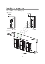
Страница 8: ...n possibly at least more than 3 meters When ice snow overlay area installs outdoor unit please add to defend snow cover Outdoor unit installed in the shade avoiding direct sunlight or high temperature heat sources of radiation Do not install in dusty or polluted place to prevent outdoor unit heat exchanger jam The outdoor unit should install in the public unapproachable place As shown below instal...

Страница 9: ...7 Installation procedure Multi Outdoor Inlet Outlet Min300mm Min300mm Min300mm Min360mm A h ...

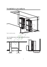
Страница 10: ...Installation procedure Case 2 stumbling block on the inlet and top side Single Outdoor Max300mm Min360mm Min 500 mm H Max300mm A Min360mm Min 500 mm H L Multi Outdoor Max300mm Min300mm Min360mm Min500mm H ...

Страница 11: ...mm Min300mm Min360mm Min500mm H L A Installation procedure Case 3 stumbling block on the outlet both right and left side Single Outdoor Not more than two sets Min1000mm Min1000mm Min300mm Min150mm Min360mm H h ...

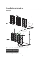
Страница 12: ...Min300mm Min1000mm Min300mm Min360mm Min1000mm H h If h H please set the outdoor on the foundation to make sure H h H The height of outdoor and foundation Note Avoid making air short cycle in any case h A 0 h 1 2H Over 600 1 2H h H Over 1400 ...

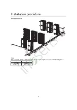
Страница 13: ...stallation procedure Multi Row Outdoor Min600mm A Min3000mm Min 360mm h h Note Make sure the distance at least 300mm between two neighbor units and no stumbling block h A 0 h 1 2H Over 600 1 2H h H Over 1400 ...

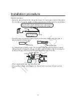
Страница 14: ...rge the nitrogen to clean the pipe The nitrogen should flow under the pressure of about 0 5Mpa and when charging the nitrogen stop up the end of the pipe by hand to enhance the pressure in the pipe then loose the hand meanwhile stop up the other end 3 The piping installation should be executed after the stop valves are closed 4 When welding the valve and the pipe cool down the valve with wet towel...

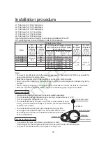
Страница 15: ...h pipes Indoor x100W Gas pipe mm Liquid pipe mm 22 28 Ø9 52 Ø6 35 36 56 Ø12 7 Ø6 35 71 140 Ø15 88 Ø9 52 226 280 Ø25 4 Ø9 52 Total indoor capacity after the branch pipe kW Gas pipe mm Liquid pipe mm 16 8KW Ø15 88 Ø9 52 16 8KW X 22 4KW Ø19 05 Ø9 52 22 4KW X 33 0KW Ø22 22 Ø9 52 33 0KW X 47 0KW Ø28 58 Ø12 7 Note Adjust the diameter on field changing pipe is needed When the latter indoor total capacity...

Страница 16: ... 1 0 1 0 1 0 1 0 1 1 Long pipe and high drop Model Item Outdoor Single way total pipe length 300m Single way pipe length Max 150m Equal Length 175m Main pipe beween outdoor to 1st branch Max 110m Equal Length 135m Pipe length between outdoors Less than 10m to 1st branch pipe Height difference between indoor and outdoor Outdoor is upper Max 50m Outdoor is lower Max 40m Height difference between out...

Страница 17: ... Branch pipe selection Total indoor capacity 100W model optional Less than 335 FQG B335A More than 335 less than 506 FQG B506A Outdoor unit type The master unit will choose the closest one to the 1st branch pipe Note 1 When connecting the outdoor branch pipe and the outdoor please pay attention to the outdoor pipe dimension 2 When adjusting the diameter among outdoor branch pipe and among the unit...

Страница 18: ...l When doing the flare connection please do the following When connecting the expanding pipe fasten the pipes with double spanner The torque refers to the former info Adhesive side Prepare on field Seal the connection and wrap the heat insulator with adhesive tape Cut off pipe with the cutter Floor Floor Right Horizontal Cut off at the middle Wrong Pipe outer diameter mm A Ø6 35 9 1 Ø9 52 13 2 Ø12...

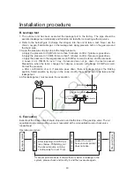
Страница 19: ...e clean The nitrogen should flow under the pressure of about 0 5Mpa and when charging the nitrogen stop up the end of the pipe by hand to enhance the pressure in the pipe then loose the hand meanwhile stop up the other end When connecting the pipes close the valves fully When welding the valve and the pipes use the wet cloth to cool down the valve and the pipes Seal the pipe end with adhesive tape...

Страница 20: ... down the test is passed Meanwhile when the temp changes for 1degree pressure will change 0 01MPa as well Correct the pressure e After confirmation of a d if pressure goes down there is leakage Check the brazing position flared position by laying on the soap modify the leakage point and take another leakage test 4 After leakage test must execute the evacuation nitrogen Hi handle gauge manifold Hi ...

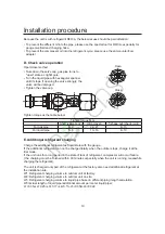
Страница 21: ...ck joint For gas pipe 8 9 22 27 8 10 For liquid pipe 5 6 13 16 8 10 Charge the additional refrigerant as liquid state with the gauge If the additional refrigerant can not be charged totally when the outdoor stops charge it at the trial mode If the unit runs for a long period in the state of lack of refrigerant compressor will occur failure the charging must be finished within 30 minutes especially...

Страница 22: ...he pipe please use the special tool for R410A especially for gauge manifold and charging hose Mark the refrigerant type in different colour on the tank R410A is pink Must not use the charging cylinder because the R410A will change when transferring to the cylinder When charging refrigerant the refrigerant should be taken out from the tank as liquid state Mark the counted refrigerant volume due to ...

Страница 23: ...other indoors and the master indoors are connected by 2 polar wires B 1 to 1 one wired controller controls one indoor as shown in above figure indoor 6 indoor 19 indoor and wired controller are connected by 3 polar wires C 2 to 1 two wired controller controls one indoor as shown in above figure indoor 20 Either of wired controllers can be set as master wired controller and the other is slave wired...

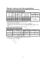
Страница 24: ...must be earthed well When power cable exceeds the range thicken it appropriately power source 3N 380 400V 50 60Hz power source 3N 380 400V 50 60Hz power source 3N 380 400V 50 60Hz power source 3N 380 400V 50 60Hz power source 3N 380 400V 50 60Hz power source 3N 380 400V 50 60Hz Item Model Power source Power cable section mm2 Wire length m Circuit breaker A Rated current of residual circuit breaker...

Страница 25: ...0A 30mA below 0 1s Power cable and communication wire must be fixed firmly Each indoor must be grounded well When power cable exceeds the range increase the gauge appropriately Shielded layer of communication wires must be connected together and be earthed at single point Communication wire total length cannot exceed 1000m Communication wire for wired controller Wire length m Wire spec Wire length...

Страница 26: ...tion 4 5 Selection item 0 0 Medium piping length 100m L 200m 0 1 Long piping length L 200m 1 0 Short piping length L 100m 1 1 Medium piping length 100m L 200m BM1_6 BM1_7 Defrosting condition α selection 6 7 Selection item 0 0 8 0 1 10 1 0 6 1 1 8 BM1_8 Silent operation selection 8 Silent mode 0 Forbidden without silent operation 1 Allow with silent operation Note The number of indoor units must b...

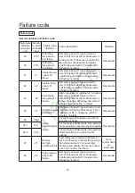
Страница 27: ... compressor is running for 5 minutes AD value is below 11 open circuit or over 1012 short circuit for 60seconds in course of startup defrosting and within 3 minutes after defrosting no alarm Resumable 24 24 Oil temp sensor Toil failure AD value is below 11 open circuit or over 1012 short circuit for 60seconds if Ta 10degree or ET 10degree within 5 minutes no alarm Resumable 26 26 0 Indoor communic...

Страница 28: ...s can be met for continous 10 seconds that is conversing successfully 1 this outdoor compressor is running normally 2 Pd Ps 0 6MPa Otherwise the system alarms reversing failure Once confirmation un resumable 36 36 Oil temp too low protection Toil In normal operation if Td CT 6 for continuous 5 minutes the unit stops and alarms 2 minutes and 50 seconds later resume automatically If it occurs 3 time...

Страница 29: ...ter fixed frequency compressor alarms inverter compressor will continue to run If fixed frequency compressor has been locked for 3 times the unit will stop and alarm Once confirmation un resumable 46 46 Communication with inverter board failure No communication within 30 seconds continuously Resumable 71 71 DC motor blocked Running at speed below 20rpm for 30s or at speed of 70 lower than the targ...

Страница 30: ...e of transducer Voltage of power source is too high 116 116 Communication abnormal between transducer and control PCB Communication is disconnected Resumable 117 117 Transducer over current software Compressor startup fails for 5 times continuously or compressor is running down till stops caused by over current or over heat 3 times in an hour confirm failure once confirmation un resumable 118 118 ...

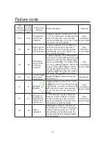
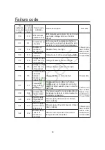
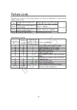
Страница 31: ...tion on master unit Indication on wired controller Flash times of LED5 on indoor PCB timer LED on remote receiver Failure code definition 01 01 1 Indoor ambient temp sensor Ta failure 02 02 2 Indoor coil temp sensor Tc1 failure 03 03 3 Indoor coil temp sensor Tc2 failure 04 04 4 Indoor TW sensor failure 05 05 5 Indoor EEPROM failure 06 06 6 Communication between indoor and outdoor failure 07 07 7 ...

Страница 32: ...evice which can stop the unit automatically when the unit runs abnormally When the high pressure switch acts the cooling heating mode will stop but the running LED on wired controller will be light still The wired controller will display failure code When the following cases occur the protection device will act In cooling mode air outlet and air inlet of outdoor are clogged In heating mode indoor ...

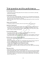
Страница 33: ...ore the unit runs If the crankcase heater is not energized for 6 hours the compressor will not work Confirm the compressor bottom getting hot Except for the condition that there is only one master unit connected no slave unit under the other conditions open fully the outdoor operating valves gas side liquid side oil equalization pipe If operating the unit without opening the valves compressor fail...

Отзывы: