19
Column Pin Assignments:
Column pin assignments are
selected from the corresponding drop down list across the top
of the matrix. Each column must have a header pin assigned to
it. Specify any pin “1” through “9” as a column.
Row Pin Assignments:
Row pin assignments are selected
from the corresponding drop down list. Each row must have a
pin assigned to it. Specify any pin “1” through “9” as a row.
*Note:
A pin cannot be assigned to both a Column and a Row.
If a conflict is detected during the matrix definition, it is indicated
in the header row/column assignment image in the upper right at
the pin position(s) being used for multiple definitions.
Single Key at a Time:
This option will lock out additional
key activations once a key has been detected. No new key
responses will be generated until all keys have been released if
this option is checked in the configuration.
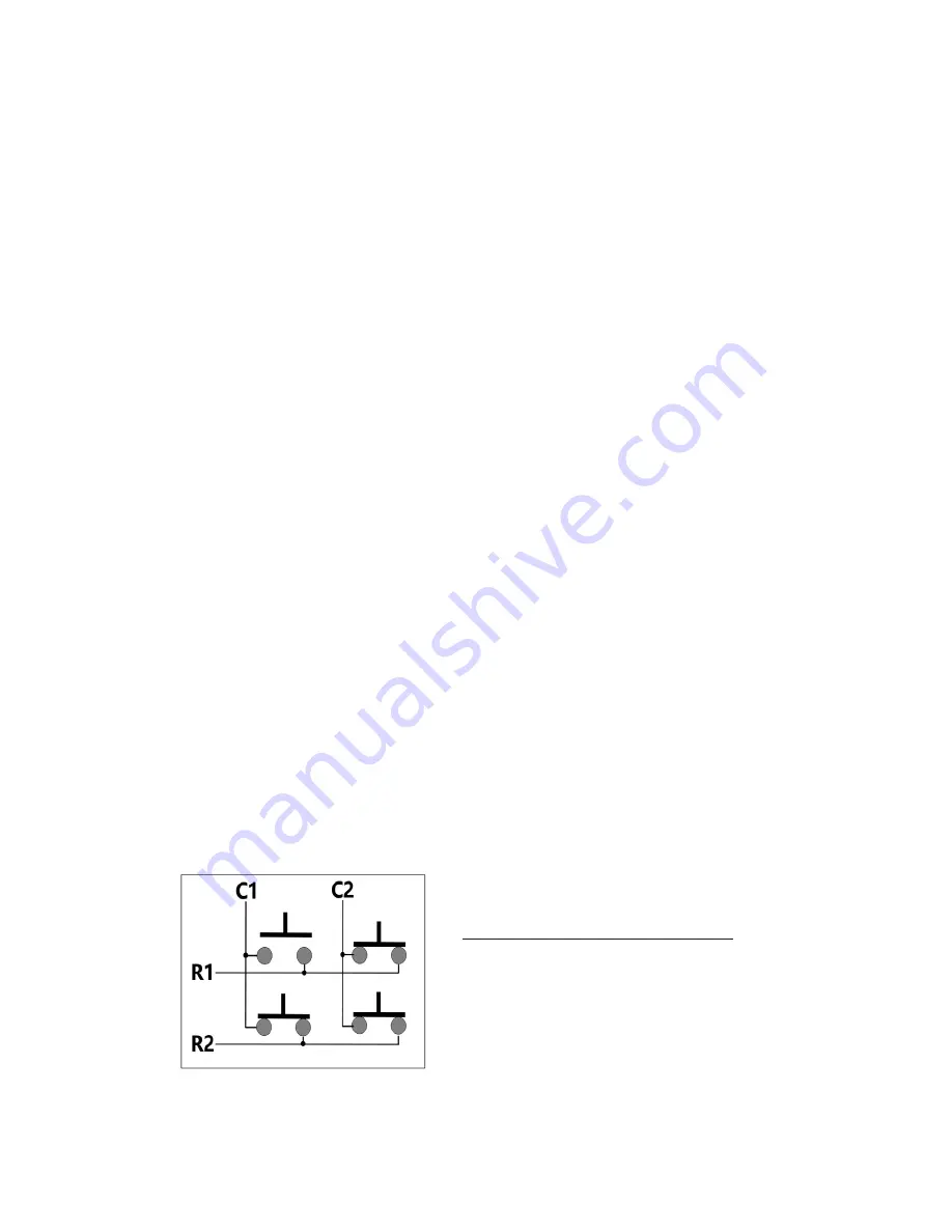
Filter Ghost Keys:
Select this option to have the KE-
USBMX20 filter out “ghost” conditions within the matrix.
Virtually any matrix has the potential for a “ghost” condition.
This condition occurs when 3 or more keys are active at the
same time and share a row and multiple columns, or a column
and multiple rows. The simple way to explain this condition is
to look at a 2 column by 2 row matrix. When 3 of any of the
keys are held, the result is that all 4 switches appear electrically
activated due to feedback of columns through the rows.
2 Column by 2 Row Matrix
When 3 switches pressed, all
4 electrically appear to be on.
If uncertain of this option, it is recommended that it be
selected.
6
The above matrix shows the keystrokes sent when keys are pressed and the
FN key is not active.
(Hold the right mouse button down while left clicking the FN key to toggle between the two matrix tables)
The matrix below shows the keystrokes sent in the same matrix when the FN
key is held active.


