background image


4600 Series Narrow Stile Trim  


Installation Instructions 


I-ED01164 

Rev 3, Rev Date: 8/4/2017 

27390048 

 Page 4 of 


Hager Companies  139 Victor Street, St. Louis, MO 63104   (800) 325-9995   www.hagerco.com 


3.


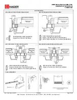
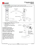
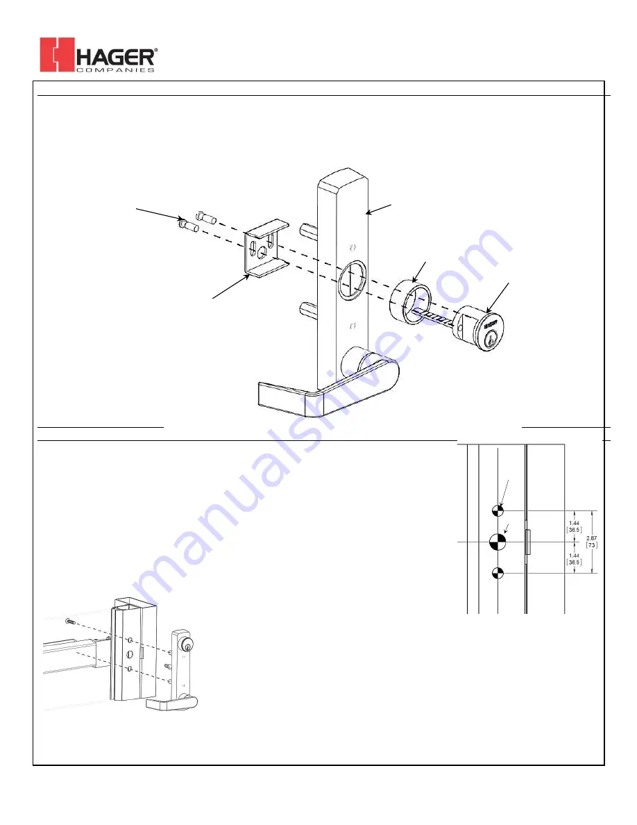
INSTALL NIGHT LATCH RIM CYLINDER (for NL trim only) 

A.


Replace standard length tailpiece with extra-long tailpiece (2-3/8”). 

B.


Install rim cylinder into collar and escutcheon trim. 

C.


Install cylinder mounting bracket from back side of escutcheon trim as shown below. 

D.


Adjust break-off screws to eliminate excess length and secure rim cylinder. 

E.


Insert key and rotate.  Observe the back of the trim and verify that the tailpiece rotates. 


4.


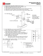
DRILL MOUNTING HOLES FOR ESCUTCHEON TRIM 

A.


Mark horizontal centerline by matching it to exit device centerline, 
which can be found on the push side of the door. 

B.


Mark vertical centerline by matching it to exit device centerline, 
which can be found on the push side of the door.  Refer to Applications 

section on page 2 to determine the location of the vertical centerline. 

C.


Apply template to door using centerlines. 

D.


Mark and drill holes as shown below. 

i.


Note that the mounting holes are the same for all functions but  
the tailpiece clearance hole is different depending on function. 

 
Note:  Available templates include T-ED01194 – 4600 Trim Template (BE, 

CE,DT) and T-ED01195 – 46NL Trim Template 


#12-24 Break-off screws 

Cylinder Mounting Bracket 

46NL 

Night Latch 

5/8” Collar 

RIM Cylinder 
Part No. 3901 
& Extra Long Tailpiece 

Part # 2-639-7058 
(Both Sold Separately) 

Door Stile 
(Pull Side) 

Frame 

Note B 

Note C 

N

ot

Note A 

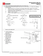
Notes: 

A.


Trim centerline corresponds to exit device centerline. 

B.


Trim mounting clearance holes (2 places): 

i.


Drill ø 1/2” [13] holes on pull side. 

ii.


Drill ø 5/16” [8] holes on push side. 

C.


Trim tailpiece clearance hole: 

i.


For CE, NK and BE functions: 
1.


Drill ø 3/4” [19] hole on pull side. 

2.


Drill ø 1/2” [13] hole on pull side. 

ii.


For NL function, drill ø 1/2” [13] thru hole. 

iii.


Not required for DT function. 

Содержание 46CE

Страница 1: ... 637 16mm Both sold separately 46BE Blank Escutcheon Always Operable 46DT Dummy Pull When Exit Device Is Dogged 46NL Night Latch Key Retracts Latchbolt Requires a RIM cylinder 3901 and extra long tailpiece 2 639 7058 Both sold separately Handing Pin Mounting Post 2 places Cylinder Cam Cylinder Nut Adjustable Tailpiece DEVICES COVERED IN THIS DOCUMENT 46CE Cylinder Escutcheon Key locks and unlocks ...

Страница 2: ...920 STANDARD STRIKE AND MULLION 4952 SEMI FLUSH STRIKE AND MULLION 4920 Standard Strike Application Single or Double Door Panic Exit Hardware 4912 strike available for fire rated applications 4952 Semi Flush Strike Application Single or Double Door Panic Exit Hardware TOOLS REQUIRED 4950 Blade Stop Strike Application Single Door Panic Exit Hardware 4920 Standard Strike Application Single or Double...

Страница 3: ... cylinder until secure Test Installation CE trim only Insert the key and rotate counterclockwise Turn the lever handle and observe the tailpiece It should be unlocked and the tailpiece will rotate Rotate the key clockwise to lock the trim Verify that the tailpiece does not rotate when the handle is turned Test Installation NK trim only Insert the key and rotate counterclockwise While keeping the k...

Страница 4: ...ich can be found on the push side of the door Refer to Applications section on page 2 to determine the location of the vertical centerline C Apply template to door using centerlines D Mark and drill holes as shown below i Note that the mounting holes are the same for all functions but the tailpiece clearance hole is different depending on function Note Available templates include T ED01194 4600 Tr...

Страница 5: ...cknesses use the closest larger size iii Slide the center shaft out until it lines up properly with the setting you chose in the last step iv Replace the screw and secure v Check for proper engagement with the exit device in the next step INSTALL ESCUTCHEON TRIM A Insert trim mounting posts and actuating shaft through door B Mate trim actuating shaft with cam on back of exit device C Secure from p...

Отзывы: