
60
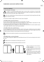
1.6 Remote control buttons
To guarantee the compatibility of the remote control with all cabinet configurations, every remote control has 4 buttons. The active control
buttons for each configuration are indicated in the respective installation and use instructions.
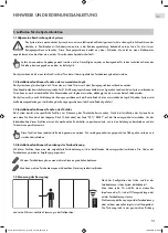
1.7 Door movement program
Each door can be moved individually. If the door meets an obstacle while moving, it will automatically stop. If a door is stopped with a
force contrary to its direction of movement, it stops and starts moving in the opposite direction.
1.8 Simultaneous movement of various doors
In certain cases, various doors may be move simultaneously in the same direction. If one of the doors is stopped by an obstacle, the other
doors will automatically stop moving in order to avoid the risk of crushing or injury.
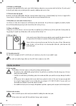
1.9 Closure of all doors
If the system is in a state with one or more doors partially or completely open, all the doors may be brought to their closed positions by
long pressing (3 seconds) any of the buttons on the remote control (see Section 1.6).
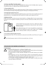
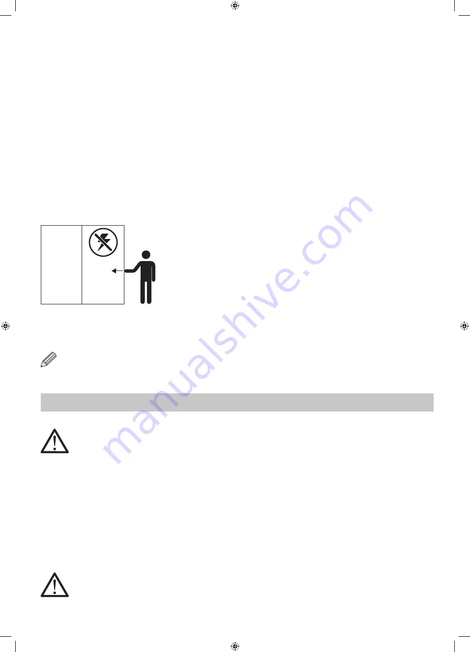
1.10 Power failure
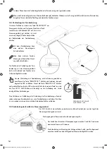
In the event of a power failure, the doors may also be moved manually, though more force will
be required due to the friction and resistance of the electromechanical system.
If power failure occurs during the movement of a door, the system will stop. When powered
again, the door will move slowly to its closed position before the system becomes fully
operational again.
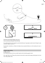
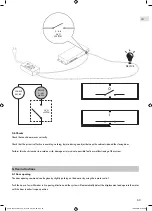
1.11 Control unit switch
The control unit is equipped with a NO switch that closes its contact every time a door is commanded to open.
The switch can handle voltages of between 0 and 48 V and a maximum current of 2A.
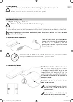
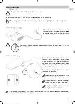
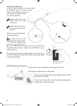
2.1 Prerequisites
2.2 Electrical connection
Make sure that the power outlet is easily accessible after installing the cabinet and system.
All connections must comply with the regulations of energy supply companies.
The installation of electrical systems must be performed by specialized personnel.
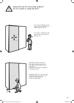
• The cabinet must be installed stably and perfectly level. Any deformity or instability in the cabinet may pose a risk to user
safety and system operation.
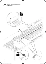
• Check the correct functioning of the sliding system to be combined with the system and the correct positioning of track limit
stops.
• Each movement bar is equipped with a 4-metre cable for connection to control unit. The control unit power supply cable
has a length of approximately 3 metres including the power adapter. A 110-240V, 50-60Hz, AC power outlet must
therefore be accessible near to where the cabinet is installed.
• The installed electrical system must comply with applicable regulations regarding active and passive electrical protection.
2. Before installation
A920_Schiebetürantrieb_für_Slido_Flat_60_FB.indd 60
19.08.2019 07:54:46
Содержание 400.50.038
Страница 15: ...15 3 A920_Schiebetürantrieb_für_Slido_Flat_60_FB indd 15 19 08 2019 07 54 26 ...
Страница 16: ...16 4 A920_Schiebetürantrieb_für_Slido_Flat_60_FB indd 16 19 08 2019 07 54 26 ...
Страница 18: ...18 Ø5 5 6 mm 5 6 A920_Schiebetürantrieb_für_Slido_Flat_60_FB indd 18 19 08 2019 07 54 27 ...
Страница 19: ...19 7 8 A920_Schiebetürantrieb_für_Slido_Flat_60_FB indd 19 19 08 2019 07 54 28 ...
Страница 20: ...20 10 9 A920_Schiebetürantrieb_für_Slido_Flat_60_FB indd 20 19 08 2019 07 54 29 ...
Страница 23: ...23 14 15 A920_Schiebetürantrieb_für_Slido_Flat_60_FB indd 23 19 08 2019 07 54 30 ...
Страница 24: ...24 16 17 18 19 A920_Schiebetürantrieb_für_Slido_Flat_60_FB indd 24 19 08 2019 07 54 31 ...
Страница 26: ...26 20 21 A920_Schiebetürantrieb_für_Slido_Flat_60_FB indd 26 19 08 2019 07 54 32 ...
Страница 29: ...29 35 17 35 25 70 24 A920_Schiebetürantrieb_für_Slido_Flat_60_FB indd 29 19 08 2019 07 54 33 ...
Страница 34: ...34 A 1 1 KONFIGURATION CONFIGURATION A920_Schiebetürantrieb_für_Slido_Flat_60_FB indd 34 19 08 2019 07 54 36 ...
Страница 35: ...35 A 1 1 1 1a A920_Schiebetürantrieb_für_Slido_Flat_60_FB indd 35 19 08 2019 07 54 37 ...
Страница 36: ...36 A 1 1 1 1b A920_Schiebetürantrieb_für_Slido_Flat_60_FB indd 36 19 08 2019 07 54 37 ...
Страница 37: ...37 A 1 1 EN 59 DE 51 A920_Schiebetürantrieb_für_Slido_Flat_60_FB indd 37 19 08 2019 07 54 37 ...
Страница 38: ...38 E KONFIGURATION CONFIGURATION 1 4 A920_Schiebetürantrieb_für_Slido_Flat_60_FB indd 38 19 08 2019 07 54 38 ...
Страница 39: ...39 E 1 1 1 1 A920_Schiebetürantrieb_für_Slido_Flat_60_FB indd 39 19 08 2019 07 54 38 ...
Страница 40: ...40 E 4 4 2 4 A920_Schiebetürantrieb_für_Slido_Flat_60_FB indd 40 19 08 2019 07 54 39 ...
Страница 41: ...41 E 1 4 EN 59 DE 51 A920_Schiebetürantrieb_für_Slido_Flat_60_FB indd 41 19 08 2019 07 54 39 ...
Страница 42: ...42 F KONFIGURATION CONFIGURATION 3 2 A920_Schiebetürantrieb_für_Slido_Flat_60_FB indd 42 19 08 2019 07 54 39 ...
Страница 43: ...43 F 2 2 2 1 A920_Schiebetürantrieb_für_Slido_Flat_60_FB indd 43 19 08 2019 07 54 40 ...
Страница 44: ...44 F 3 3 3 2 A920_Schiebetürantrieb_für_Slido_Flat_60_FB indd 44 19 08 2019 07 54 41 ...
Страница 45: ...45 F 3 2 EN 59 DE 51 A920_Schiebetürantrieb_für_Slido_Flat_60_FB indd 45 19 08 2019 07 54 41 ...
Страница 49: ...49 4 3 mm 3 A920_Schiebetürantrieb_für_Slido_Flat_60_FB indd 49 19 08 2019 07 54 44 ...
Страница 67: ...A920_Schiebetürantrieb_für_Slido_Flat_60_FB indd 67 19 08 2019 07 54 46 ...


