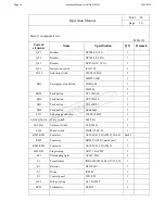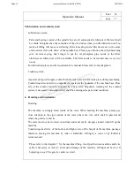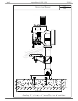
Operation Manual
Total 26
Page 15
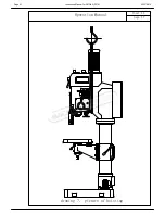
drawing(5-2)picture of electric element of machine
clutch
AC27V
KM1
KM2
74
L
13
69
Q1
KM6
70
6
I1
+24V
N
15
71
6
rotate in clockwise
SB2
FU21(1A)
16
24
COM
4
N1
Q2
66
YC1
YC
brake
I7
reverse rotate
reverse rotate
KM6
I4
I3
I2
SX1
18
17
SB3
switch
SQ1
SQ4
22
stop
73
start/stop for feed
out/in for tapping
tapping
SB4
19
V1
R1
HL2
FU22(3A)
72
U1
L1
12
I6
I5
SQ3
limit position(above) for feed
SQ2
20
limit position (below) for feed
21
SB5
25
Q3
61
SB6
72
KM1
62
KM2
65
Q4
63
KM2
KM1
64
rotate in clockwise
jog
I8
WJ1-8/5F picture of connecting wire
emergency stop
SB1
23
67
Q5
SX2
68
KM3
coolant pump
Attention: The diameter of the line without indicating is 0.75mm .
2
black
brown
blue
black
blue
brown
Page 17
Instruction Manual for GHD-50 (D178)
23/12/2014


