background image

-  In the event of a power cut, the specific start-up 

button must be reset. 

ACCIDENT PREVENTION AND 
SAFETY REGULATION 

-  The machine has been tested in conformity with 

point 20 of EN 60204 

This machine has been designed to comply with 
national and community accident- prevention 
regulations. Improper use and/or tampering with 
the safety devices will relieve the manufacturer of 
all responsibility. 


1.1 

Advice for the operator 

-  Check, the line voltage is the same as the 

voltage required by the machine’s motor.  

-  Check the efficiency of your electric supply and 

grounding system; connect the power cable of 
the machine to the socket and the ground lead 
(yellow- green in color) to the grounding system. 

-  When the machine is in suspended mode (or 

stopped) the blade must not move. 

-  Only the blade section used for cutting must be 

kept unprotected. To remove guards to expose 
more of the cutting blade adjust the blade 
guides. 

-  It is forbidden to use the machine without its 

shields  

-  Always disconnect the machine from the power 

socket before blade change or carrying out any 
maintenance job, even in the case of abnormal 
machine operation. 

-  Always wear suitable eye protection. 
-  Never put your hands or arms into the cutting 

area while the machine is operating. 

-  Do not shift the machine while it is cutting. 
-  Do not wear loose clothing like: shirts with 

sleeves that are too long, gloves that are too big, 
bracelets, chains or any other object that could 
get caught in the machine during operation.  Tie 
back long hair. 

-  Keep the area free of miscellaneous object; i.e. 

equipment, tools, etc… 

-  Perform only one operation at a time.  Never 

have several objects in your hands at the same 
time.  Keep your hands as clean as possible. 

-  All internal operations, maintenance or repairs, 

must be performed in a well-lit area or where 
there is sufficient light from extra sources to 
avoid the risk of accidents. 


1.2 

The electrical equipment according to 
European Standard" CENELEC EN 
60204-1" 

1.3 

Warning labels 


-  The electrical equipment ensures protection 

against electric shock as a result of direct or 
indirect contact.  The active parts of this 
equipment are housed in a box to which access 
is limited by screws that can only be removed 
with a special tool; the parts are fed with 
alternating current as low voltage (24V).  The 
equipment is protected against splashes of 
water and dust. 

-  Protection of the system against short circuits is 

ensured by means of rapid fuses and grounding; 
in the event of a motor overload, protection is 
provided by a thermal probe. 


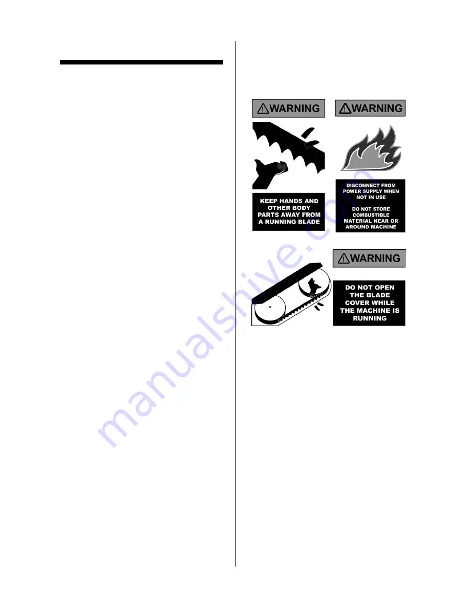
Replace warning labels if they become obscured 
or removed. 
-  Keep hands and other body parts away from a 

running blade. 

-  Do not open the blade cover while machine is 

running. 

-  Do not store combustible materials near or 

around machine.  

-  Always wear approved safety glasses/face 

shields while using this machine. 

-  Keep machine guards in place at all times. 
-  Do not wear gloves. 
-  Remove loose clothing and confine long hair. 
-  Keep the work area clean and free 

miscellaneous objects. 


1.4 

Emergencies according to European 
Standard “CENELEC EN 60204-1” 

-  In the event of incorrect operation or a danger 

condition, the machine may be stopped 
immediately by pressing the red mushroom 
shaped button. 

NOTE:  Resetting of machine operation after each 
emergency stop requires resetting the emergency 
stop button. 


3

Instruction Manual for BS-460AS (B035)

31/03/2016

Содержание BS-460AS

Страница 1: ...INSTRUCTION MANUAL BS 460AS Dual Mitre Swivel Head Metal Cutting Band Saw 415V 600 x 440mm W x H Rectangle B035 1 Instruction Manual for BS 460AS B035 31 03 2016 ...

Страница 2: ...de Roller adjustment 7 4 4 Adjusting the cutting precision 7 4 5 Blade tracking adjustment Manual blade tension type 7 4 6 Blade tracking adjustment Hydraulic blade tension type 8 4 7 Placing the saw blade onto the drive wheel and flywheel 8 4 8 Hydraulic vise pressure 8 5 OPERATION PREPARATIONS 8 5 1 Setting the stroke limit 8 5 2 Positioning the vise 9 5 3 Angle cutting 9 5 4 Using the vise 9 5 ...

Страница 3: ...nly one operation at a time Never have several objects in your hands at the same time Keep your hands as clean as possible All internal operations maintenance or repairs must be performed in a well lit area or where there is sufficient light from extra sources to avoid the risk of accidents 1 2 The electrical equipment according to European Standard CENELEC EN 60204 1 1 3 Warning labels The electr...

Страница 4: ...pace should be left around the machine to allow safe handling of materials inspection and maintenance operations Take precautions to choose a location that will keep the machine free of vibration and dust caused by other machinery Place a spring washer and washer on each hex head bolt Face the long side of the bracket up Align the holes of short side of the bracket to the machine panel s holes Pla...

Страница 5: ...side to prevent coolant spray on to the floor Mobile coolant tray 2 6 Securing to foundation Position the machine on a flat and level foundation of reinforced concrete Level machine and anchor it to the foundation with anchor bolts Maintain a minimum distance of 800mm from the rear of the machine to the wall Position the anchors using screws and expansion plugs or tie rods sunk in cement 2 7 Level...

Страница 6: ...eral government so they may be set aside for collection by the public waste disposal service 3 Old mineral and synthetic and or mixed oils emulsified oils and greases are considered hazardous or special refuse so they must be collected transported and disposed of at a special waste disposal service NOTE The standards and legislation concerning refuse is in a constant state of evolution therefore i...

Страница 7: ...s equipped with automatic power shut off safety device to prevent any further damage when a blade has been broken There is a reduction in tension when an adjustment bolt actuates micro switch s plunger To keep the micro switch in proper contact with the blade s tension An adjustment of the actuator bolt is required 3 8 Chip brush This model has a powered chip brush driven by an axle transfer from ...

Страница 8: ...angle scale 3 13 Attached coolant device An attached coolant device that is screwed on the front vise jaw for supply enough coolant to the cutting material This device can be unscrewed and move to the rear vise jaw for easy both side miter cutting 4 SET UP AND PRE OPERATIONS 4 1 Adjusting the tungsten carbide guides The blade is guided by the upper ball bearings side ball bearings and tungsten car...

Страница 9: ... accomplished by a qualified personnel that are familiar with this type of adjustment Disconnect the machine from power supply Loosen the adjusting bolts X slightly if needed Use the setscrews X1 to adjust the direction of the guide blocks After adjusting tighten the adjusting bolts X 4 5 Blade tracking adjustment Manual blade tension type This adjustment must be accomplished by qualified personne...

Страница 10: ...ade into the rollers of the left and right blade guide The back edge of the saw blade should make contact with the flange of the drive and flywheel turn clockwise the blade tension handle to tighten the saw blade until the blade is properly tensioned Replace the blade guards Use the blade running switch 3 1N to check the proper ride of the blade 4 8 Hydraulic vise pressure The hydraulic vise press...

Страница 11: ... the hydraulic vise toward other side Visually check clearance of the blade and saw bow against the hydraulic vise Readjust the position if necessary Lock the hydraulic vise in position using its lock handle 5 3 Angle cutting 5 4 Using the vise The hydraulic vise operates automatically and can be controlled using the control panel Use the vise open switch 3 1F and vise close switch 3 1G to open an...

Страница 12: ...ase blade tension by turning the blade tensioning handle counter clockwise until blade is free Remove the old blade from both wheels and out of each blade guide Caution Even dull blades are sharp to the skin Use extra caution handling band saw blades Position the blade and making sure that the teeth are pointed downward in the cutting direction Position the blade on the wheels Make sure back of th...

Страница 13: ... and re connect the power 5 10 Laser guide device optional The laser guide has been set correctly before shipment The laser guide line works when machine power on the red line will align and close with the blade if any situations have to readjust Laser device see below pictures A screw for moving the device forward or backward B screw for moving the device downward or upward Loosen C thumb knob fo...

Страница 14: ...will flash in warning After cutting the saw bow has taken more than 40 sec to rise to the start position the power will shut off The upper stroke limit indicator light will flash in warning Turn on the main connect switch A on the door of electrical box Turn the key to automatic operation mode L1 to unlock the machine The indicator light B should be lit After pressing the start button the vise cla...

Страница 15: ...ing 7 4 Six monthly maintenance Test the continuity of the equipotential protection circuit 7 5 Oils for lubricating coolant Considering the vast range of products on the market the user can choose the one most suited to their own requirements using as reference the type SHELL LUTEM OIL ECO THE MINIMUM PERCENTAGE OF OIL DILUTED IN WATER IS 8 10 7 6 Oil disposal 7 7 Special maintenance Special main...

Страница 16: ...erating unload was 71db Noise level during the cutting of mild carbon steel was 73db NOTE with the machine operating the noise level will vary according to the different materials being processed The user must therefore assess the intensity and if necessary provide the operators with the necessary personal protection as required by Law 277 1991 16 Instruction Manual for BS 460AS B035 31 03 2016 ...

Страница 17: ...17 Instruction Manual for BS 460AS B035 31 03 2016 ...

Страница 18: ...18 Instruction Manual for BS 460AS B035 31 03 2016 ...

Страница 19: ...19 Instruction Manual for BS 460AS B035 31 03 2016 ...

Страница 20: ... Bolt M8x16 2 71 Hex Socket Cap Screw M6x30 1 19 Coolant Pump 1 72 Hinges Ø8x50 2 20 Hex Cap Bolt M6x12 2 73 Main PC Board WT M1 1 21 Washer M6 2 74 Control Panel 1 22 Pump Plate 1 74 1 Control PCB 1 23 Button Head Socket Screw M6x12 2 75 Counter 1 24 Plate 1 76 Button Head Socket Screw M5x8 10 25 Button Head Socket Screw M6x8 4 77 Key Lock Power Switch 1 37 Hydraulic Unit 1 78 Cutting Feed Rate 1...

Страница 21: ...et Cap Screw M8x20 2 118 Hex Socket Cap Screw M8x20 2 171 Vise Jaw Left 1 119 Set Block 1 172 Vise jaw Right 1 120 Button Head Socket Screw M6x8 2 173 Hex Socket Cap Screw M10x30 8 121 Cover 1 174 Hex Socket Cap Screw M8x20 4 121 1 Hex Socket Cap Screw M4x6 2 175 Vise Plate 1 121 2 Magnifier Holder 1 176 Hex Socket Cap Screw M8x20 1 121 3 Angle Magnifier 1 177 Hex Socket Cap Screw M12x30 2 122 Hex...

Страница 22: ...t 1 268 2 Spring Washer M8 2 222 Pin Ø6x28 1 268 3 Washer M8 2 223 Screw Sleeve 1 269 Wing Screw M6x10 1 224 Set Handle M12x45 1 270 Spring Washer M6 1 225 Rod 1 271 Hex Socket Cap Screw M6x20 1 226 Set Screw M8x8 1 272 Brush Shaft 1 227 Sleeve Rod 1 273 Nut M20 1 228 Shaft 1 274 Brush Rod 1 229 1 Mobile Fence 1 274 1 Key 4x15 4 230 Set Screw M8x8 1 275 Universal Joint 2 231 Blade Cover 1 275 1 Se...

Страница 23: ...Set Block 2 318 Hex Socket Cap Screw M10x30 4 373 Hex Cap Bolt M10x20 1 319 Taper Bearing 32009 2 374 Nut 1 320 Idle Wheel 1 375 Spring Washer 1 321 Anti Dust Cover 32009AV 2 376 Washer 1 322 Star Washer AW09 1 377 Sensor Bracket 1 323 Nut AN09 1 378 Sensor 1 324 Cover Switch 1 379 Round Head Screw M4x10 2 325 Hex Socket Cap Screw M4x30 2 380 Cover 1 326 Nut M8 2 381 Button Head Socket Screw M5x8 ...

Страница 24: ... Hex Cap Bolt M12x25L 4 482 Slider Seat 1 427 Spring Washer M12 4 483 Idle Wheel Shaft 1 428 Washer M12 4 484 Movable Coolant Tray 2 429 Outlet Support 1 485 Hex Cap Bolt M6x12L 4 430 Big Round Head Screw M6x12L 2 486 Tray Bracket 2 431 Handle 1 487 Nut M6 4 432 Movable Support 1 488 Nut 1 2 2 433 Side Support Plate 1 489 Adjusting Screw 2 434 Flat Head Screw 5 16 x3 4 L 4 490 Cock 1 4x1 4 1 435 W...

Страница 25: ...UE 460DSA 1000307 V4 25 Instruction Manual for BS 460AS B035 31 03 2016 ...

Страница 26: ...UE 460DSA 1000307 V3 26 Instruction Manual for BS 460AS B035 31 03 2016 ...

Страница 27: ...UE 460DSA 1000307 V3 27 Instruction Manual for BS 460AS B035 31 03 2016 ...

Страница 28: ...UE 460DSA 1000307 V3 28 Instruction Manual for BS 460AS B035 31 03 2016 ...

Страница 29: ...UE 460DSA 970912 V2 29 Instruction Manual for BS 460AS B035 31 03 2016 ...

Страница 30: ...UE 460DSA 1000622 V1 30 Instruction Manual for BS 460AS B035 31 03 2016 ...

Отзывы: