background image


13


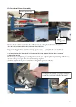
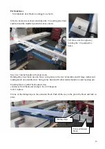
Fit front fence 
    Sit aluminum riser block on outrigger as shown   

Sit fence on its side as shown and align the 2 x locating pins front 
and back and the middle lock down bolt as shown.  

Tilt fence over the right way 
locating the 3 in perspective 
holes.            

Screw in 1 ratchet handle to front pivot pin.  
Holding alloy riser block up onto fence, swing fence to the rear of machine and fit large washer and 
locking Knob onto middle stud.  Swing fence back and fit other ratchet handle to outer locating pin.  

Ensuring fence is pulled back against stop,  
( slid away from blade and swung to be on 90 degrees)   
lock it in place.  

Fit one of the sliding stops to the extension block. Push all the way to the pin in the block and lock in 
place.   


Fence extension 
block 

Sliding stops 

Содержание PS-3200

Страница 1: ...1 11 3 10 W724 HAFCO WOODMASTER PS 3200 PANEL SAW ASSEMBLY AND SET UP INSTRUCTIONS ...

Страница 2: ...r blue door of the main saw stand to gain access and remove the cardboard box with blades operation instructions tools and other small parts and accessories Remove all other packing and accessories Read safety and operation instructions supplied Position machine Remove machine off wooden skid and Position machine in final position Please note the machine needs a working area of 7200mm x 5000mm wit...

Страница 3: ...d open up electrical cabinet Ensure machine is not connected to power Position fork in front of saw bench and with assistance roll over table assembly onto its top Lift off and position table on saw body locating 3 x sliding pins in the 3 x holes on table base Screw in and finger tighten only each end attachment bolt Being careful not to disturb any electrical wiring Table base assembly can now be...

Страница 4: ...and slide table all the way to the right table should be 40 45mm as shown With table in this position This will give you access to the hole for the middle table attachment screw hole fit screw up and under into hole and tighten it firmly Check table slides freely full travel both directions Set table back in centre and lock table lever Refit access cover and close electrical cabinet Sliding table ...

Страница 5: ...pport arm onto spigot of arm and locate spring loaded pin into Swivel location engagement bracket Bracket may need adjusting to suit Up down and in out adjust up down positioning of bracket so when location pin is up in hole it is flush with top of plate Further adjustment may be needed when setting blade guard over blade Guard outrigger arm Guard support arm Swivel Location bracket Set height of ...

Страница 6: ...verhead guard The guard will now need adjusting to fit safely and correctly Swing guard assembly over blade position and lock in place if not already done Firstly adjust the guard so it is over the blade opening central to the blade opening and parallel to the blade slot Do this by adjustment of the swivel location bracket the guard attachment pin horizontal and vertical slots And the main guard o...

Страница 7: ...lable more adjustment can be obtained by adjusting the draw bar turnbuckle under the sheet metal guard running underside of the guard arm Fit the dust collector hose from the rear of the guard arm to the fitting on the side of the 100mm lower stand outlet Top of hose fits into overhead arm Hold in with Duct tape And the bottom of hose fits on with hose clamp supplied Check guard is set correctly a...

Страница 8: ...n Sit a straight edge across the main table and sliding table to get extension table were needed Fit Rear table extension 500 x 900 to rear of main table This is held on with 4 x socket head cap screws and can be adjusted up from any fall by screwing in the 4 x lower cap screws as needed and hitting the table were it is bolted on with a soft hammer up and down Sit a straight edge across the main t...

Страница 9: ...d can be seen just coming out of each nut Pushing the studs down onto the adjustment bolts in the slots tighten up these 2 nuts Carefully slide on the fence sliding casting Note the position of lock lever The pin may have to be pushed in to slide lock clamp over shaft Slide the casting up to the main table Fit the fence extrusion onto the sliding casting lock in place and then slide the fence asse...

Страница 10: ...ully sliding the fence assembly out off the main table and onto the sheet metal outrigger table the level of the outrigger table can be adjusted as needed up or down so the roller of the sliding fence casting transitions smoothly over the join The outrigger table may also need adjusting of its tilt as well to ensure the fence doesn t scrape With the fence now all the way out its parallelism with t...

Страница 11: ...ews from above the fence rod and fit the RHS measuring assembly This will need setting later when blade is put on machine Fit Push stick mount onto top of sliding casting as shown Slide fence out over onto sheet metal extension table and adjust table as needed ...

Страница 12: ...ng table is in a locked position fit the sliding carriage onto the location bolt of the outrigger extension arm at the same time sliding the table hooks in from the front end of the sliding table Slide assemble to the middle of the sliding table and lock in position Using a straight edge across the sliding table over to the roller on the outrigger table check and adjust height as needed by undoing...

Страница 13: ... to front pivot pin Holding alloy riser block up onto fence swing fence to the rear of machine and fit large washer and locking Knob onto middle stud Swing fence back and fit other ratchet handle to outer locating pin Ensuring fence is pulled back against stop slid away from blade and swung to be on 90 degrees lock it in place Fit one of the sliding stops to the extension block Push all the way to...

Страница 14: ... screw on a small magnifying line Fit magnifying sight large one to fence extension arm Fit thigh pushing bar Remove plastic plug from end of tube that has drilled hole in Remove 2 x nuts off screw in frame and refit as shown with 2 x lock nuts locked together and RHS can still swing freely Refit plastic end cap Pushing bar ...

Страница 15: ...tting scribe blade turns anti clockwise in use With large double ended spanner and 10mm allen key supplied fit key in spindle hole and undo nut anti clockwise Remove nut and support flange completely Fit scribe blade then flange and nut do up nut tightly using opposite forces against allen key Fit main blade turns clockwise in use With large double ended spanner and 10mm allen key supplied fit key...

Страница 16: ...The measurement tape in the aluminum extrusion can now be set to 200cm under the magnifier line by unscrewing small knob under the fence sliding the tape in the slot as needed and locking the knob again NB ends of metal tape in the slot may have to be trimmed to suit Final adjustment can be done after taking a test cut and re measuring at a later date Ensuring machine is not connected to power Set...

Страница 17: ... positioning of the guard may need to be done again as per directions explained previously The height of the blade guard must always be set with the bottom of the guard down to the thickness of the material being cut This is adjusted by releasing the lock nut on the rear upright of the blade arm assembly and turning the socket head cap screw as needed UP anti clockwise to move the guard closer to ...

Страница 18: ...it does not have licensed electrician reverse the phase direction of the power to the machine Retest as above and when all is correct switch on the SCOURER BLADE This should go anticlockwise NB the Scouring blade will not operate unless the main blade is switched on The Blade Angle LED may be flashing If so press and HOLD down the small red reset button under the LED panel for 10 to 20 seconds LED...

Страница 19: ...is used at all times Setting scouring blade The Scouring or Scriber blade will need to be set when used Left and right adjustment is done by the Right hand Screw Up and Down adjustment is done by the Left hand Screw Guard for tilted blade Guard for 90 degree cut Adjusts Scouring blade left and Right Clockwise moves blade to the Left Adjusts Scouring blade Up and Down Lock Nuts To be locked in plac...

Страница 20: ... and tilt it to 30 degrees This will give you easier access to change the belt Disconnect the power from the machine and open the rear door to the machine base Loosen the belt tensioning nuts on the tension lever and carefully move both belts over to the set of pulleys required Below picture is shown set up on Low speed Belt tensioning nut One on top of block not shown and one below block ...

Страница 21: ...gitudinal cutting knife 9 fixed board 10 nut 11 connection board 12 following action board 13 bolt 14 cushion 15 plywood 16 bolt 17 protection hood 18 circumgyrating base 20 guide track 21 bolt 22 pipe block 23 dust collection pope 24 guide track 25 circumgyrating base 26 cushion 27 bolt 28 lift nut 29 lift screw 30 gimbal 31 handwheel 32 handle 33 bolt 34 angle bolt 35 angle nut 36 lift adjusting...

Страница 22: ...motor base 4 c u s h i o n 5 connection board 6 adjusting sheath 7 triangular belt 8 main spindle wheel 9 motor wheel 10 pressure cushion 11 main spindle sheath 12 bearing 13 pressure cushion 14 main spindle 15 adjusting screw 16 saw nip plate 17 nut ...

Страница 23: ...bolt 23 scorning saw turning base 24 spring 25 oriented spindle 26 motor base 27 nut 28 pressure cushion 29 scoring saw spindle 30 bearing 31 scoring saw sheath 32 bearing 33 sheath 34 driving belt 35 scoring saw wheel 36 pressure cushion 37 motor wheel 38 pressure cushion 39 motor 40 torsion spring ...

Страница 24: ...er 12 3 bolt 13 4 urgent stop switch 14 5 board base 15 6 operation button 16 7 nut 17 8 sheath 18 9 nut 19 10 eccentric spindle 20 adjusting spindle hair brush stop head roll wheel bearing bearing spindle of turning arm hair brush the pipe of turning arm lug ...

Страница 25: ...Screw 24 Pad 6 Stabilizer nail 25 Stud 7 Lock block 26 Ejector block 8 Clip 27 Bracket 9 Screw 28 Shaft 10 Pad 29 Carriage roller 11 Pad 30 Bearing 12 Eccentric shaft 31 Nut 13 Handle 32 Cap 14 Plug 33 Support 15 Screw 34 Pad 16 Platen 35 Nut 17 Revolving shaft handle 36 Angle scale seat 18 Pad board 37 Angle scale 19 Screw ...

Страница 26: ...lug 13 Stop board 14 Shaft 15 Screw 16 Magnifier 18 Screw 19 Magnifier 20 Fixing block 21 Screw bolt 22 Plug 23 Draw rod 24 Stabilizer nail 25 Screw 25 Extension ruler 29 Ruler 30 Ruler 31 Fixing block 32 Plug 33 Fixing block 34 Nut 36 Pad 37 Holding plate 38 Pad 39 Screw 40 Sleeve 41 Screw 42 Board 43 Screw 44 Eccentric shaft 45 Handle 46 Sleeve 47 Screw 48 Hand screw 49 Lug ...

Страница 27: ...axle guide shaft axle 18 Push handle 4 Pad 19 Push handle seat 5 Supporting bolt 20 Screw 6 Screw cap 21 Handle 7 Screw cap 22 Handle shaft 8 Lock plate 23 Eccentric shaft 9 Board 24 Pad 10 Screw 25 Clip 11 Shaft 26 Handle shaft 12 Screw 27 Handle 13 Eccentric sleeve 28 Eccentric shaft 14 Small shaft 29 Sleeve 15 Pad 30 Clip ...

Страница 28: ...ble 1 Sliding table 2 S c r e w 3 S c r e w 4 H a n d l e 5 Handle terminal plate 6 Locking handle 7 Locating plate 8 Fixing block 9 S c r e w 1 0 Connecting strip 1 1 S c r e w 1 2 Terminal plate 13 Track metal strip ...

Страница 29: ...29 9 Sliding track seat 1 track seat 2 cap 3 screw 4 adjustment screw bolt 5 nut 6 keeping bracket 7 steel ball 8 lock plate 9 connecting strip 10 track metal strip ...

Отзывы: