background image

2

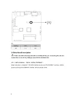
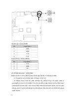
HD LED Pins (J4 pin3,pin4 for HDD LED) 

As  a  rule,  there  is  a  HD  LED  on  the  panel  of  chassis,  while  HD  device  (like  hard  Disk)  is 
reading  or  writing  (no  matter  which  HD  device),  LED  will  flash,  shows  that  IDE  device  is 
running. Connect IDE LED on chassis panel and these pins (pin3 is LED anode)


3

Buzzer Pins

  Pin5/Pin6 for SPEAKER


To connect external speaker pins   

4

Reset Button Pins(pin7,pin8 for RESET ) 

Connect this pins and RESET switch on panel of chassis with cable. When system can not 
work  on,  reset  can  make  system  restart,  without  turning  on/off  the  power,  thereby  it  can 
prolong system life span 

5

Power On/Off Control Pins (pin9, pin10 for POWER BUTTON) 

Connect these two pins with bounce switch on panel of chassis,    to switch-on or switch-off the 
power. 

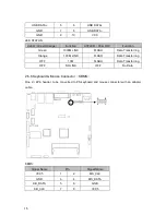
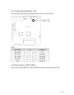
2.5.13 SO-DIMM Slot

SO-DIMM


Board with one single channel SO-DIMM slot supports DDRIII 800/1066 RAM upto 4GB.   

22

Содержание BIS-6650

Страница 1: ...Owner s Manual BIS 6650 Intel Dual Core Atom D2550 Large Screen Digital LED Signage System ...

Страница 2: ...e for any direct indirect intended or unintended losses and or hidden dangers due to improper installation or operation Before ordering products please learn about the product performance from the distributors to see if it is in line with your needs The contents of this manual are protected by copyright law All rights are strictly reserved Any form of unauthorized reproduction including but not li...

Страница 3: ...e prod uct please ensure that all power cables for the devices are un plugged when adding or removing any devices or reconfiguring the system 7 To prevent electrical shock disconnect the power cable from the electrical outlet before relocating the system 8 When adding or removing components to or from the system ensure that all the power cables for the system are unplugged pri or to installation o...

Страница 4: ...es Description 9 2 5 1 SATA Interface SATA1 SATA2 PWROUT 9 2 5 2 Serial Ports COM 10 2 5 3 Display Interfaces VGA DVI LVDS 11 2 5 4 LVDS Backlight Control Interface J2 13 2 5 5 USB Ports USB_LAN1 USB_LAN2 USB56 J6 14 2 5 6 Keyboard Mouse Connector KBMS 15 2 5 7 Programmable Input Output Interface JGP 16 2 5 8 Power Interface PWR1 PWR2 16 2 5 9 FAN Connector CPU_FAN 17 2 5 10 JLPC JLPC 18 2 5 11 Au...

Страница 5: ...n 28 3 2 4 SATA Configuration 30 3 2 5 USB Configuration 31 3 2 6 Supper IO Configuration 32 3 2 7 H W Monitor 33 3 2 8 Serial Port Console Redirection 33 3 3 Chipset Menu 34 3 3 1 South Bridge 34 3 4 Boot Menu 35 3 5 Security Menu 37 3 6 Save Exit Menu 37 Section 4 Install and Replace Computer Components 39 4 1 Remove Computer Cover 40 4 2 Replace DIMM 41 4 3 Install CF Card 41 4 4 Mounting Brack...

Страница 6: ...Please check your package carefully according to the checklist below If you find any components lost or damaged please contact your retailer Item QTY BIS 6650 1 User Manual 1 Drivers and Utilities 1 DVI Cable 1 Power Adaptor 1 Wall Mount Bracket 1 Screws 1 ...

Страница 7: ... Intel Atom N2800 D2500 D2550 CPU System offers high performance with industrial grade reliability Rich I O 4x USB2 0 2x COM 1x VGA 1x DVI D 2x LAN 1x Mini PCIe SSD optional The industrial grade embedded boards SSD support VGA and DVI interface and compact fanless design make BIS 6650LC a perfect solution for Kiosk Digital Signage LED controlling Advertising and other embedded applications 1 ...

Страница 8: ...11E 10 100 1000Mbps 2x LAN USB 4x USB2 0 Serial Port 1x RS 232 DB9 1x RS 232 485 Dispaly 1x VGA 1x DVI D Cooking System Fanless ICEFIN cooking design Audio 1x Mic in 1x Line out Expansions 1x PCI LED card reserve location 1x Mini PCIe System LED PWR_LED System Control Power ON OFF swtich PS 2 N A Power Power Supply DC 12V power adapter Reliability Mounting Desktop or Wall Mount Operating Temp 0 55...

Страница 9: ... Line in 3 2x COM 9 2x USB 2 0 4 DVI 10 VGA 5 2x Gigabit Ethernet 6 Line out 7 LED Controller 8 10 7 9 2 4 5 6 3 2 BIS 6650 Rear View 3 1 3 Product Indicator Diagram 1 BIS 6650 Front View 1 Power ON OFF Button 1 ...

Страница 10: ...tallation procedures Improper installation of any components will lead to system malfunction Note Before installation please put on the anti static gloves in case that the static electricity causes damage to the motherboard MITX 6936 Dimension Diagram 2 2 Installation Steps Please follow the steps below to assemble your computer 1 Refer to the manual and adjust all the jumpers of MITX 6936 2 Insta...

Страница 11: ...before installing the RAM module 1 First please algin the notch of the memory bank with the notch on the socket and press the memory bank slowly into the socket 2 Please choose the proper memory bank that matches your motherboard 2 4 Jumper Settings Please refer to following instructions to do jumper settings before installing your hardware devices Remark How to identify the PIN1 of all jumpers an...

Страница 12: ...y to enter BIOS setting and reload optimal defaults 4 Save and Exit JCC Setting JCC 1 2 BIOS back to intialization factory dafault 2 3 Normal Status System default Do not clear CMOS when the computor is power on otherwise it will cause damage to the motherboard 6 ...

Страница 13: ...on Power On JAT JAT Setting JAT Open Disable this auto boot function Close Enable this auto boot function 2 4 3 COM2 Jumper Setting J1 J2 J1 J2 jumpers are used to configure COM2 transmission mode COM2 supports RS232 RS485 Default mode as RS232 7 ...

Страница 14: ...2 4 4 LVDS Rated Voltage Select Jumper J8 Before using the LVDS please first check the rated operating voltage COM2 RS232 default COM2 RS485 J1 1 3 2 4 J1 3 5 4 6 J2 1 2 J2 3 4 5 6 8 ...

Страница 15: ...ns carefully before you connecting the external connectors in case of any damage caused to the motherboard 2 5 1 SATA Interface SATA1 SATA2 PWROUT Board provides 2x standard 7 Pin SATA interfaces and one 5Pin PWROUT interface HDD is power up through the PWROUT interface with an adapter cable 9 ...

Страница 16: ...Pin Signal Name 1 GND 2 TX 3 TX 4 GND 5 RX 6 RX 7 GND PWROUT Pin Signal Name 1 12V 2 GND 3 VCC 4 GND 5 VCC3 2 5 2 Serial Ports COM Board provides 2x standard DB9 serial ports Reserved two Pins JCOM1 JCOM2 10 ...

Страница 17: ...al Name 1 DCD 2 RXD 3 TXD 4 DTR 5 GND 6 DSR 7 RTS 8 CTS 9 RI 2 5 3 Display Interface VGA DVI LVDS 1x standard DB15 VGA port 1x DVI D 1x standard single channel 18 24bit LVDS port Reserved one 2 5 Pin VGA Pin optional 11 ...

Страница 18: ...2 GREEN 7 GND 12 SDA 3 BLUE 8 GND 13 HSYNC 4 NC 9 5V 14 VSYNC 5 GND 10 GND 15 SCL DVI Signal Name Pin Signal Name TDC2 1 2 TDC2 GND 3 4 NC NC 5 6 SC DDC SD DDC 7 8 NC TDC1 9 10 TDC1 GND 11 12 NC NC 13 14 VCC GND 15 16 HP DETECT TDC0 17 18 TDC0 GND 19 20 NC NC 21 22 GND 12 ...

Страница 19: ...C 1 2 VCC GND 3 4 GND LA_DATA_N0 5 6 L_DDC_DATA LA_DATA_P0 7 8 L_DDC_CLK GND 9 10 GND LA_DATA_N1 11 12 LA_CLK_N LA_DATA_P1 13 14 LA_CLK_P GND 15 16 GND LA_DATA_N2 17 18 LA_DATA_N3 LA_DATA_P2 19 20 LA_DATA_P3 2 5 4 LVDS Backlight Control J2 J2 Pin Signal Name 1 12V 2 BKLT_EN 13 ...

Страница 20: ...he one 2x 5Pin header can be converted into 2x standard USB ports Both sides of the RJ45 network interface with a LED lamp The yellow one indicates the data transmission status The green one indicates the network link status J6 is the LAN LED for LAN 1 and LAN2 Standard USB Ports Pin Signal Name 1 5V 2 USB DATA 3 USB DATA 4 GND USB_56 Signal Name Pin Signal Name VCC 1 2 GND USB DATA 3 4 GND 14 ...

Страница 21: ...ata Transferring Orange 100M LINK FLASH Data Transferring OFF 10M FLASH Data Transferring OFF NO LINK OFF No Data 2 5 6 Keyboard Mouse Connector KBMS One 2 4Pin header to be converted to PS keyboard and mouse connector with an adapter cable KBMS Signal Name Pin Signal Name VCC5 1 2 MS_CLK GND 3 4 MS_DATA KB_DATA 5 6 GND KB_CLK 7 8 VCC5 15 ...

Страница 22: ...it GPIO one 2x 5Pin header GPIO Signal Name Pin Signal Name SIO_GP30 1 2 VCC SIO_GP31 3 4 SIO_GP34 SIO_GP32 5 6 SIO_GP35 SIO_GP33 7 8 SIO_GP36 GND 9 10 SIO_GP37 2 5 8 Power Interface PWR1 PWR2 Inbuilt power interface PWR1 is reserved PWR2 is the default external power interface 16 ...

Страница 23: ... following remarks 1 The electric current of the FAN 350mA 4 2W 12V 2 Please check if the fan cable matches the socket wiring The power cable is generallythe red one in the middle Then the grounding cable black and the FAN speed pulse signal out cable other color Some FANs without speed detect function but the output voltage upto 12V which will damage the motherboard Recommend to use FANs with spe...

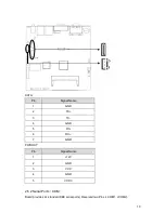
Страница 24: ...CPU_FAN Pin Signal Name 1 GND 2 12V 3 Speed detect 2 5 10 JLPC JLPC Board provides one 2 10Pin JLPC Low Pin Count Interface Specification to connect external devices 18 ...

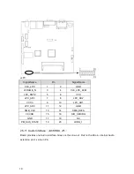
Страница 25: ..._AD3 7 8 LPC_AD2 VCC3 9 10 LPC_AD1 LPC_AD0 11 12 GND SMB_CLK 13 14 SMB_DATA 3 3VSB 15 16 SIO_SERIRQ GND 17 18 NC PM_SUS_STAT 19 20 LDRQ_1 2 5 11 Audio Interface JACKHDA J11 Board provides one Audio interface Green is the Line out Red is the Mic in Internal Audio extension pin 1x Line in Pin 19 ...

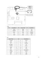
Страница 26: ...ered LED Screen Control Hardware Platform J11 Pin Signal Name 1 AGND 2 LINE_IN_L 3 LINE_IN_R 2 5 12 Front Panel Connector JFP One 2x 5Pin front panel pin is used to connect all the function buttons and LED Lamp on the front panel 20 ...

Страница 27: ...g guide to connect and pay attention to its anode and cathode Improper connection will lead to system malfunction POWER LED HDD LED BUZZ RESET BUTTON PWR BUTTON 1 System Power LED Pins pin1 pin2 for PWLED Connecting system power LED cable to these pins pin 1 is LED anode when system power switch on power LED on When system power switches off power LED off 21 ...

Страница 28: ...ect external speaker pins 4 Reset Button Pins pin7 pin8 for RESET Connect this pins and RESET switch on panel of chassis with cable When system can not work on reset can make system restart without turning on off the power thereby it can prolong system life span 5 Power On Off Control Pins pin9 pin10 for POWER BUTTON Connect these two pins with bounce switch on panel of chassis to switch on or swi...

Страница 29: ...ll remove static electricity during the assembly process During operation please keep touching the unpainted metal surface it will be useful for static electricity discharge 3 1 Install Computer Peripheral Accessories 3 1 1 DVI Interface Connection Both the motherboard and the LED controller board have one DVI port Motherboard will send video signal to LED controller card DVI interface of LED cont...

Страница 30: ...ps below to install drivers 1 Press the Pop up button of front drive 2 Please place the Drivers and Utilities disk into the CD ROM tray 3 Slightly push back tray 4 Please click the relevant menu item from the auto run menu 5 Double click the driver and then you can install it according to the screen prompts 6 After finishing the installation of some drivers the system will prompt you to restart yo...

Страница 31: ...parameter finally the operating system will take control BIOS is the communication bridge between hardware and O S Correct configuration of BIOS is critical for maintaining system stability and its optimized performance BIOS Settings 1 Power on or reboot the computer self detection information will show 2 When message shows as Press DEL to enter setup please press DEL then enter into BIOS SETUP Pr...

Страница 32: ... 1 86GHz Memory Information Memory Frequency 1067 MHz DDR3 Total Memory 2048 MB System Date Mon 08 10 2012 System Time 08 50 24 Select Screen Select Item Enter Select Change Opt F1 General Help F9 Optimized Defaults F10 Save Exit ESC Exit Version 2 10 1208 Copyright C 2010 American Megatrends Inc System Time System time format Hour Minute Second System Date System Date Format Week Month Day Year 3...

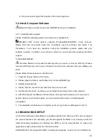
Страница 33: ...0 American Megatrends Inc Launch LAN1 2 PXE OpROM Enables or disables the boot option for legacy network devices connected to LAN1 and LAN2 3 2 1 ACPI Settings BIOS SETUP UTILITY ACPI Settings Select the highest ACPI sleep state the system will enter when the SUSPEND button is pressed ACPI Sleep State S1 CPU Stop Clock Select Screen Select Item Enter Select Change Opt F1 General Help F9 Optimized ...

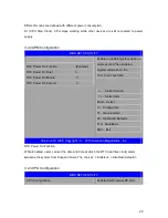
Страница 34: ...tion Enabled RTC Power On Hour 0 RTC Power On Minute 0 RTC Power On Second 0 Select Screen Select Item Enter Select Change Opt F1 General Help F9 Optimized Defaults F10 Save Exit ESC Exit Version 2 10 1208 Copyright C 2010 American Megatrends Inc RTC Power On Function When Enabled users can set the date and time at which the RTC real time clock alarm awakens the system from Suspend mode The choice...

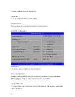
Страница 35: ...ange Opt F1 General Help F9 Optimized Defaults F10 Save Exit ESC Exit Version 2 10 1208 Copyright C 2010 American Megatrends Inc The read only option contains detailed information of CPU including CPU manufacturer model frequency L1 Cache L2 Cache etc Hyper Threading Disable or enable the Hyper Threading Technology Intel Hyper Threading Technology uses resources efficiently enabling multiple threa...

Страница 36: ...e system to dynamically adjust processor voltage and core frequency which can result in decreased average power consumption and decreased average heat production CPU C state Report Enable or disable the CPU C states 3 2 4 SATA Configuration BIOS SETUP UTILITY SATA Configuration SATA Ports 0 3 Device Names if Present and Enabled Serial ATA Port1 Not Present Serial ATA Port2 Not Present Serial ATA C...

Страница 37: ... Storage Devices KingstonDataTraveler G2 PMAP Auto Select Screen Select Item Enter Select Change Opt F1 General Help F9 Optimized Defaults F10 Save Exit ESC Exit Version 2 10 1208 Copyright C 2010 American Megatrends Inc USB function This option is used to enable or disable the USB port USB 2 0 EHCI Support Enabled Enable USB EHCI USB 2 0 functions max transmission rate upto 480Mpbs Disabled Disab...

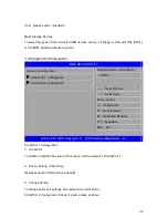
Страница 38: ...ort 2 Configuration Select Screen Select Item Enter Select Change Opt F1 General Help F9 Optimized Defaults F10 Save Exit ESC Exit Version 2 10 1208 Copyright C 2010 American Megatrends Inc Serial Port 1 Configuration 1 Serial Port To enable or disable the serial port functions Set Parameters of Serial Port 1 2 Device Setting Read Only Display serial port IRQ and base address 3 Change Setting To c...

Страница 39: ... Enter Select Change Opt F1 General Help F9 Optimized Defaults F10 Save Exit ESC Exit Version 2 10 1208 Copyright C 2010 American Megatrends Inc PC Health Status PC Health Status Detect BIOS will display current system temperature CPU temperature FAN rotate speed and related voltage value 3 2 8 Serial Port Console Redirection BIOS SETUP UTILITY COM1 Console Redirection Disabled Console Redirection...

Страница 40: ... 10 1208 Copyright C 2010 American Megatrends Inc Console Redirection To enable or disable the console redirection function 3 3 Chipset Menu BIOS SETUP UTILITY North Bridge Parameters South Bridge Select Screen Select Item Enter Select Change Opt F1 General Help F9 Optimized Defaults F10 Save Exit ESC Exit Version 2 10 1208 Copyright C 2010 American Megatrends Inc 3 3 1 South Bridge BIOS SETUP UTI...

Страница 41: ...oss To select the computer starting up status after restoring the AC power Power Off press the power buttong to start the computer Power On Computer starts up directly after restoring the AC power Last State Return to the last status when the AC power loss Bypass Power On Enable or disable the bypass function when system power on Bypass Power Off Enable or disable the bypass function under Power O...

Страница 42: ...in the preset time system will continue to start Bootup Numlock State This function allows users to activate Numlock function when system boots up ON Numlock open when boot up OFF Numlock under cursor control Show Full Logo Enabled Computer boot screen will show supplier s LOGO Disabled Self detect info will show when system boots Boot Option 1 2 System will detect devices according to the preset ...

Страница 43: ...ults F10 Save Exit ESC Exit Version 2 10 1208 Copyright C 2010 American Megatrends Inc The password length Min 1 character Maximum 20 characters Administrator Password To setup administrator password User Password To setup user password If you have set the password system will display Installed If not system will display Not Installed 3 6 Save Exit Menu BIOS SETUP UTILITY Load Defaults Save Change...

Страница 44: ...ght C 2010 American Megatrends Inc Load Defaults Restore Load Default values for all the setup options Save Change and Exit Press Enter to select this option and press Enter to confirm to save all BIOS changes and Exit Discard Change and Exit Press Enter to select this option and press Enter to confirm to discard all changes and exit 38 ...

Страница 45: ...tton for 4 seconds Before disassembling or assembling the computer components Please follow the safety instructions below which will help to protect the computer from potential damage and personal injury Please be careful to deal with components and plug in cards and please do not touch their connection points Please hold the edges of the cards or metal bracket If take other components such as pro...

Страница 46: ...e disconnect the power cable from the computer before you go to remove the top cover of the chassis Before touching any components of the computer please make sure your hand touch an unpainted metal surface it will remove the static electricity during the assembly process 1 Please read and follow the steps mention in the section Before disassembling or assembling the computer components Make sure ...

Страница 47: ...nd push the memory into the socket onboard then press down the memory 6 Mount the L shape bottom cover 7 Connect the computer and devices with power supply line then turn on power 8 Right click the My Computer icon on the desktop and then click the Properties 9 Click General option tab 10 If you want to check the installation please check the listing memory size 4 3 Install CF Card BIS 6650 provid...

Страница 48: ...t the L shape bottom cover 4 4 Mounting Bracket 1 Take out the wall mount bracket and follow the pictures below to align the screw holes and install the wall mount barcket to the base panel of BIS 6650 2 Then please place the BIS 6592LC to the right position and screw it tightly 42 ...

Страница 49: ...er 2 Right click my computer select management and go to Device Manager 3 Right click display controller in the menu of graphic card select Properties click Driver select update driver 4 Select Show the list of all drivers which are designated locations so that choices can be made from it select next 5 Select the location of display driver click ok 6 Implement the installation restart the system P...

Страница 50: ...f unsigned char temp outportb indexp 0x87 outportb indexp 0x87 unlock outportb indexp 0x2d temp unsigned char inportb datap temp 0xfe outportb indexp 0x2d outportb datap temp set pin for watchdog outportb indexp 0x07 outportb datap 0x08 outportb indexp 0x30 outportb datap 0x01 enable logical device outportb indexp 0xf5 outportb datap 0x00 set second outportb datap 0x08 set minute outportb indexp 0...

Страница 51: ...outportb indexp 0xf7 outportb datap 0x00 outportb indexp 0xaa lock 45 ...

Страница 52: ...he bus number is 0 device number is 18 and function number is 0 This interface is using the 3rd basic address register According to PCI standard the basic address are allocated by the BIOS dynamically and it is a MUST normally to obtain the basic address before program this interface if there are no other PCI expansion device the basic address is CC00H GPIO s interface debugging program is attache...

Страница 53: ...n PC It will do hardware testing while system booting then system runs it provides an interface between OS and hardware BIOS is stored in a ROM chip BUS In a computer system it s the channels among different parts for exchanging data it s also a group of hardware line BUS here means part lines inside CPU and main components of memory Chipset Integrated chips for executing one or more function Here...

Страница 54: ...ronics for connecting HDD CD ROM device IRDA Infrared Data Association for short here means infrared transmit interface to connect infrared transmit devices This sort of device transmits data by infrared light wave without connecting any cables It have been developed a standard now LAN Network interface Network grouped by correlative computers in a small area generally in a company or a building L...

Страница 55: ...interrupted testing operation to the system including RAM keyboard hard disk driver etc Check them in normal situation and work well PS 2 A keyboard mouse connective interface specification developed by IBM PS 2 is a DIN interface with only 6PIN it also can connect other devices like modem USB It is the Universal Serial Bus for short A hardware interface adapts to low speed external devices and is...

Страница 56: ...21015 Commerce Pointe Drive Walnut CA www habeyusa com Copyright 2013 Habey USA All Rights Reserved Version 1 0 ...

Отзывы: