
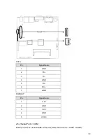


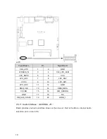


JFP:
Signal Name
Pin
Signal Name
POWER LED+
1
2
POWER LED-
HD LED+
3
4
HD LED-
VCC
5
6
BUZZDATA-
RESET BUTTON
7
8
GND
POWER BUTTON
9
10
GND
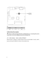
Please refer to following guide to connect and pay attention to its anode and cathode.
Improper connection will lead to system malfunction.
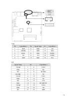
POWER LED
HDD LED
BUZZ
RESET BUTTON
PWR BUTTON
1
)
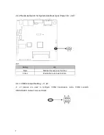
System Power LED Pins ( pin1, pin2 for PWLED)
Connecting system power LED cable to these pins, (pin 1 is LED anode),when system power
switch on, power LED on
;
When system power switches off, power LED off
21


