ES0755 rev A 1/11
27
1. With no tool in the machine, command a tool change. Press Emergency Stop before the double arm
reaches the spindle. This will cause the mill to move the Y and Z axes to the ATC position.
2. Verify the spindle is free to rotate without hitting the double arm. If necessary, use the T/C Recovery
commands to move the arm further from the spindle.
3. Using T/C Recovery, orient the spindle.
4. Using T/C Recovery, rotate the double arm in the forward direction. Continue rotating the double arm until it
reaches the spindle, then extends approximately 6” (152.4 mm) in front of the spindle.
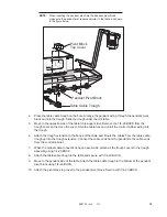
5. Using the dowel pin as a handle, install the tapered half of the split tool into the spindle. Be careful to not
place your hands in the pinch point between the tool and the spindle. The Tool Release button operates in a
Toggle On/Off mode during Tool Recovery. Press once to activate the Tool Release; press again to clamp.
6. Remove the dowel pin, and install the second half of the split tool into the end of the double arm in front of
the spindle. It will be necessary to manually press the tool lock plunger (near the center of the shaft as shown
in the Service manual) to allow the spilt tool to be inserted.
7. Using T/C Recovery in the reverse direction, move the double arm back toward the spindle until the halves
of the split tool are approximately 1” (25.4 mm) apart.
8. Continue to move arm toward spindle. Watch double arm as it approaches spindle. The spindle dogs and
slots in the double arm should line up. This verifies Parameter 257 (Spindle Orient Offset). If spindle and arm
do not line up, reset Parameter 257 as described in Service Manual, and continue moving closer until there is
a maximum of 1/8” (3.2 mm) gap between the split tool halves, ensuring the halves do not touch each other.
9. Check the X and Y alignment of the double arm to the spindle by inserting the alignment dowel through
both halves of the split tool. The dowel should slide freely. If the pin does not slide freely, the direction of the
misalignment may be determined by feeling the “step” between the split tool halves, by using a steel rule,
straight edge, or similar tool.
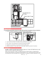
10. If misalignment is present, adjust the leveling screw under the tool changer mount. Verify machine level
before continuing.
11. Using T/C Recovery, move the double arm in the forward direction, away from the spindle. Remove both
halves of the split tool.
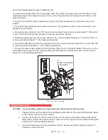
12. Install a tool holder into the double arm, measure the distance from the front of the double arm to the front
face of the tool holder (see diagram), and record the distance.
Measure the distance from the
surface of the double arm to
the surface of the tool holder
A
6
5
1
2
3
4
5
6
7
8
8
9
9
1
Made in America
Tool Changer
Double Arm
Tool Holder
Measure This
Distance
80
7
0
6
0
90
0
5
0
40
30
2
0
1
0
13. Remove the tool from the double arm. Using T/C Recovery, move the arm in the reverse direction to the
spindle. Continue until the arm rotates to the origin “Home” position. Once the arm is away from the spindle,
insert the same tool holder used in Step 13 into the spindle.
14. Using T/C Recovery, rotate arm forward until it is very close to the tool holder. The spring-loaded slide is
depressed as arm nears the tool holder, but be sure that arm is not touching the tool holder itself.


