ES0755 rev A 1/11
22
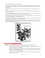
8. Next, thread the four intermediate leveling bolts (four bolts with 30mm hex heads located near the center of
each side of the base plate) down until they just touch the leveling blocks. Further tighten bolts approximately
another 1/8 turn past this point to insure these screws are each sharing some portions of the load.
9. Complete the base plate installation by installing the nuts and washers onto the threaded ends of the tool
changer anchor bolts and tightening to 230 ft-lb. Note that these are metric threads and nuts.
10. Remove the two shipping brackets located on the tool changer’s arm assembly.
11. Install the tool changer guard around the tool changer and make the following electrical connections:
a. Connect the remote control box cable to the tool changer junction box.
b. Route and connect cables from tool changer junction box to connectors located on side of control box.
38 Tool Side Mount Tool Changer Alignment
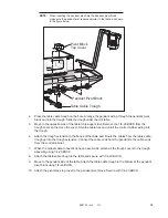
1. Level the tool changer using a magnetic level placed on the body of the tool changer. Set perpendicularity
to A and Z axis using the four leveling screws and jam nuts at base of the tool changer.
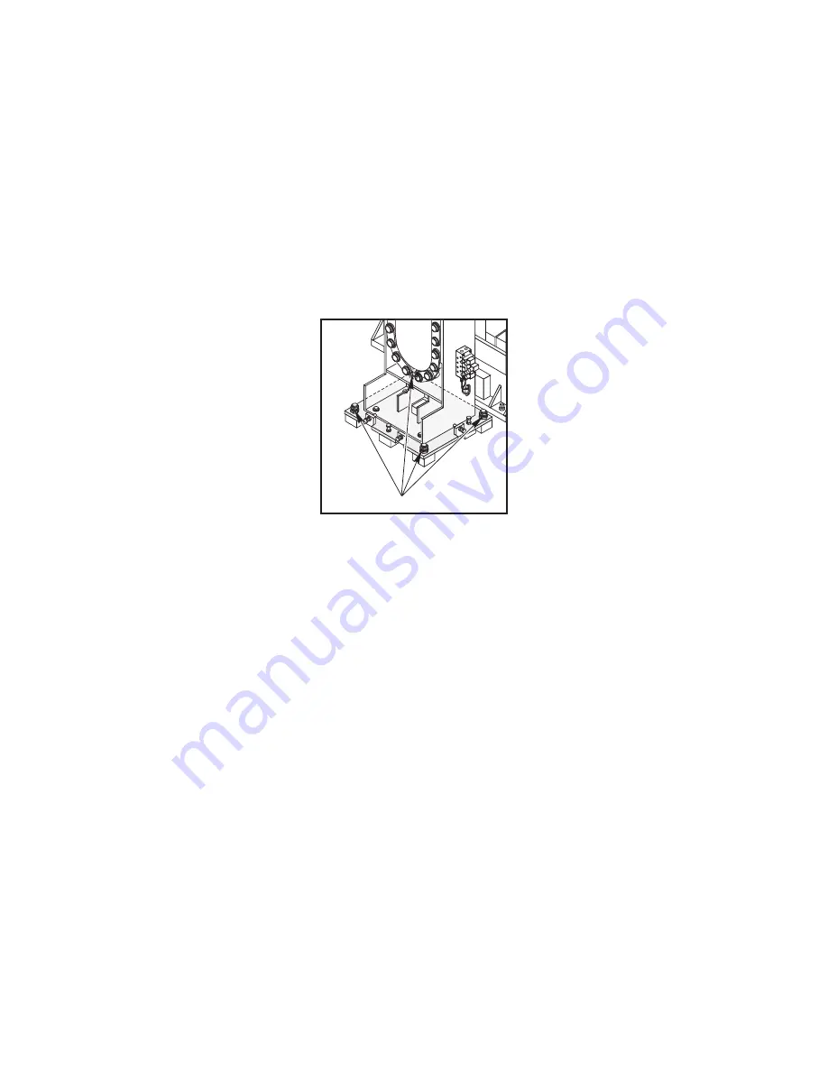
Leveling Screws
Leveling Screw Locations
The four hex screw that go through the hollow leveling screws are used to anchor the tool changer to the floor
after it has been leveled. Insure that the tool changer angle bracket is attached.
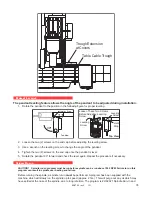
2. Loosen the eight sub plate bolts.
Do Not press POWERUP RESTART.
3. To align tool changer, a few preliminary steps must be done to avoid damaging the mill or the tool changer:
a. Press
<POWER ON>
button.
b. Go to the
PARAMETERS
screen and set
Parameters #211
(Y-axis) and
#64
(Z-axis ) to zero.
c. Press
<ZERO RETURN>
and
<AUTO ALL AXIS>
buttons.
d. Press
<MDI>
button then press
<ORIENT SPINDLE>
button.
e. Press
<TOOL CHANGER RESTORE>
button.
At this point the machine will ask the operator to verify the locations of any tools and the status of the tool
changer door. When the conditions asked for on the screen are met press
<Y>,
this will simultaneously open
the tool changer door and to move the next screen.
This screen gives a warning that tools may fall during the following process. The operator is asked to press
<Y>
to continue the process. The new screen states:
PRESS A TO ATTEMPT AUTO RECOVERY
PRESS M TO GO TO MANUAL RECOVERY
Press
<M>
to go into manual recovery mode.
The next screen states:
A= Arm
M= Magazine
O= Open Door
C= Close Door
Press
<M>
on the keypad to home the tool changer magazine. After the magazine has reached its home


