ES0755 rev A 1/11
20
4. Connect the power cord from the hydraulic power unit’s motor to the power connection located on the side
of the milling machine’s control box.
5. Check the rotation direction of the hydraulic power unit motor using the following procedure:
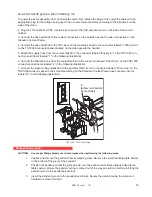
a. Remove the orange inspection cover from the bell housing located between the motor and the
hydraulic pump. Power-up the machine but
do not clear the alarms until the next step
.
b. With an observer watching the coupling inside the inspection window, push the <
RESET
> button
on the keypad and immediately push the <
E-STOP
> button. This will jog the motor on the hydrau-
lic power unit.
c. Note the rotational direction of the power unit motor and compare with the directional arrow lo
-
cated on the front of the hydraulic pump casing.
d. If the rotation matches the rotation of the directional arrow the machine is correctly wired. If the
rotation does not match then the phasing of the machine’s power must be changed by reversing
any two of the incoming three wires of the machine’s power wiring.
e. If it was necessary to change the machine phasing , recheck and verify that the motor is rotating
in the correct direction (return to Step 5b).
6. Turn the hydraulic power unit on by powering-up the machine and clearing the alarms. Note that the
hydraulic power unit operates any time the machine is powered-up and the alarms are cleared.
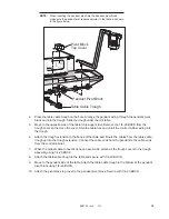
7. When the pump is to be operated for the first time, the discharge side of the pump should be in a no-load
state. This is accomplished by connecting the pump’s discharge (pressure) hose directly to the inlet of the
return filter connection.
Start and stop the motor 5 to 6 times to bleed any air from inside the pump. Verify that the pump is
discharging oil by feeling the discharge hose or cracking one of the fittings. Operate the pump for at least 10
minutes without any load to remove any remaining air in the circuit.
8. To adjust the flow rate of the hydraulic system perform the following steps:
a. The flow rate is adjusted with the hydraulic power unit operating in a no-load state.
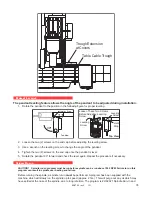
b. Install a hydraulic service flowmeter rated for 1 to 15 gpm in-line with the hose connecting the
pump discharge to the filter inlet of the hydraulic power unit.
c. Turn the hydraulic power unit on and adjust the pump discharge flow rate by turning the flow ad
-
justment screw (the horizontally oriented screw with locknut), clockwise to decrease the flow rate
and counter-clock wise to increase the flow rate. The correct flow rate for operation of the ATC
38 tool changer is 8 gpm. Note that it may be necessary to first adjust the pump “open system”
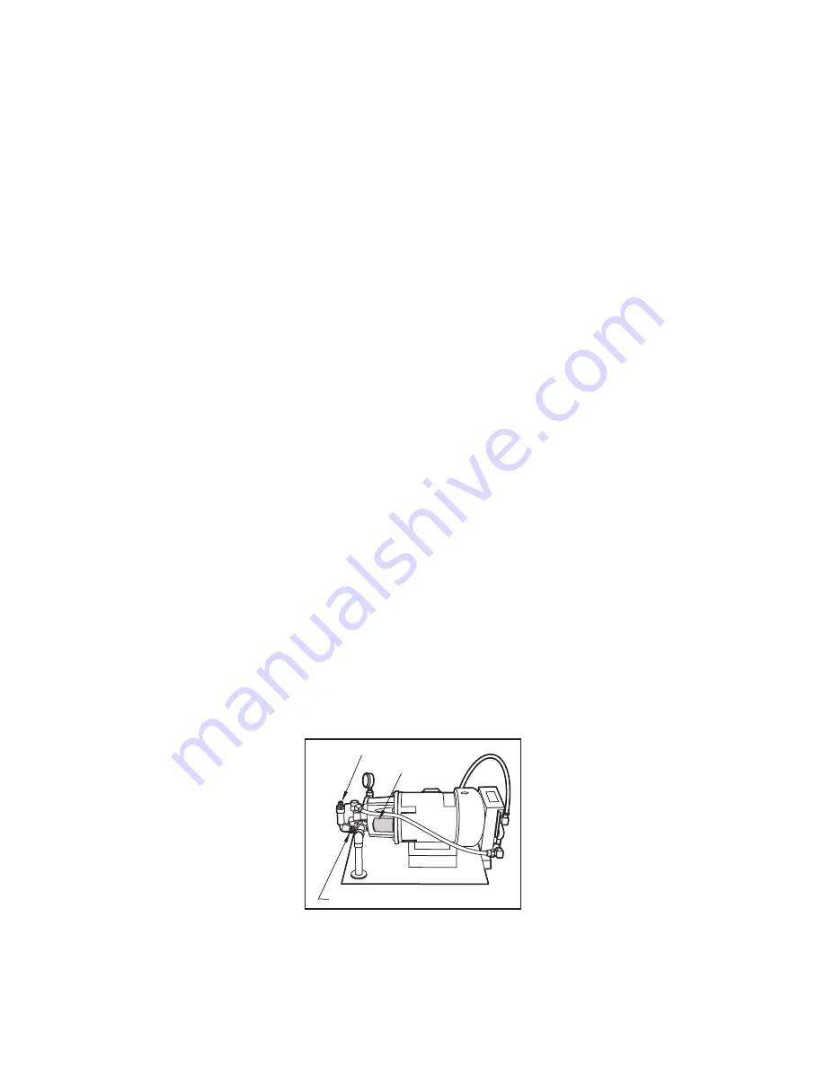
discharge pressure to achieve 8 gpm. This is done by adjusting the vertically oriented screw. Ap-
proximately 300 to 375 psi will be the maximum achievable pressure when in the “open system”
operating mode.
Inspection Cover
Flowrate Adjustment Screw
Pressure Adjustment Screw
Hydraulic Pump Pressure and Flowrate Adjustment Screws
9. Reconnect the hydraulic hoses as described in Step 2, after the flow rate has been adjusted.
10. Turn the machine on and check the pressure gage on the HPU to verify that the system pressure is in the


