background image


9-3 

Figure9-3 Straight-through cable 


Figure9-4 Crossover cable 


Select an Ethernet twisted pair cable according to the RJ-45 Ethernet port type on your device. An 
RJ-45 Ethernet port can be MDI (for routers and PCs) or MDIX (for switches). 

Table9-3

 an

Table9-4


show their pinouts.  

Table9-3 RJ-45 MDI port pinouts 

Pin 

10Base-T/100Base-TX 

1000Base-T 

Signal 

Function 

Signal 

Function 

Tx+ 

Sends data 

BIDA+ 

Bi-directional data cable A+ 

Straight-through cable

white/orange

orange

white/green

blue

white/blue

green

white/brown

brown

1

2

3

4

5

6

7

8

white/orange

orange

white/green

blue

white/blue

green

white/brown

brown

1

2

3

4

5

6

7

8

Crossover cable

white/orange

orange

white/green

green

white/orange

orange

white/green

blue

white/blue

green

white/brown

brown

1

2

3

4

5

6

7

8

blue

white/blue

white/brown

brown

1

2

3

4

5

6

7

8

Содержание SecPath L5030

Страница 1: ...H3C SecPath L5030 L5060 L5080 L5000 E Load Balancer Installation Guide New H3C Technologies Co Ltd http www h3c com Document version 6W103 20221101 ...

Страница 2: ...r respective owners Notice The information in this document is subject to change without notice All contents in this document including statements information and recommendations are believed to be accurate but they are presented without warranty of any kind express or implied H3C shall not be liable for technical or editorial errors or omissions contained herein Environmental protection This prod...

Страница 3: ...er literally as shown Italic Italic text represents arguments that you replace with actual values Square brackets enclose syntax choices keywords or arguments that are optional x y Braces enclose a set of required syntax choices separated by vertical bars from which you select one x y Square brackets enclose a set of optional syntax choices separated by vertical bars from which you select one or n...

Страница 4: ...ns Convention Description Represents a generic network device such as a router switch or firewall Represents a routing capable device such as a router or Layer 3 switch Represents a generic switch such as a Layer 2 or Layer 3 switch or a router that supports Layer 2 forwarding and other Layer 2 features Represents an access controller a unified wired WLAN module or the access controller engine on ...

Страница 5: ...hardware model configuration or software version It is normal that the port numbers sample output screenshots and other information in the examples differ from what you have on your device Documentation feedback You can e mail your comments about product documentation to info h3c com We appreciate your comments ...

Страница 6: ...erface module 2 7 Installing a hard disk 2 8 Connecting Ethernet cables 2 9 Connecting a copper Ethernet port 2 9 Connecting a fiber port 2 9 Connecting the power cord 2 11 Connecting the AC power cord 2 11 Connecting the DC power cord 2 12 Verifying the installation 2 13 3 Accessing the device for the first time 3 1 Setting up the configuration environment 3 1 Powering on the device 3 1 Checking ...

Страница 7: ... loss 6 2 High operating temperature 6 2 Software loading failure 6 2 7 Appendix A Chassis views and technical specifications 7 1 Chassis views 7 1 Front panel 7 1 Rear panel 7 1 Interface numbering 7 2 Interface modules 7 2 NSQM1TG8A 7 2 NSQM1QG2A 7 3 NSQM1G4XS4 7 3 NSQM1GT8A 7 4 NSQM1GP8A 7 4 NSQM1GT4PFCA 7 4 Power modules 7 5 AC power module 7 5 DC power module 7 5 Technical specifications 7 6 ...

Страница 8: ...General safety recommendations Make sure the installation location is flat vibration free and away from electromagnetic interferences ESD and anti slip measures are in place Do not place the device on an unstable case or desk The device might be severely damaged in case of a fall Keep the chassis and installation tools away from walk areas Keep the chassis clean and dust free Do not place the devi...

Страница 9: ...tach a dust cap to any open optical fiber connector and a dust plug into any open fiber port or transceiver module port to protect them from contamination and ESD damage Moving safety When you move the device follow these guidelines To avoid damage move and unpack the device with care After you move the device from a location below 0 C 32 F to the equipment room follow these guidelines to prevent ...

Страница 10: ...e captive screws and circuit failure High temperature can accelerate the aging of insulation materials and significantly lower the reliability and lifespan of the device Table1 2 Temperature and humidity requirements Item Specification Temperature Operating Without hard disks 0 C to 45 C 32 F to 113 F With hard disks 5 C to 40 C 41 F to 104 F Storage 40 C to 70 C 40 F to 158 F Humidity Operating W...

Страница 11: ...air vents The installation site has a good cooling system The device provides either of the following airflow for heat dissipation by installing different fan trays Rear to front airflow The FAN 20F 2 A fan tray blows air from the power module side to the port side as shown in Figure1 1 The fan tray has a blue fan tray handle Front to rear airflow The FAN 20B 2 A fan tray draws air from the port s...

Страница 12: ...ing guidelines If AC power is used use a single phase three wire power receptacle with protection earth PE to filter interference from the power grid Keep the device far away from radio transmitting stations radar stations and high frequency devices Use electromagnetic shielding for example shielded interface cables when necessary To prevent signal ports from getting damaged by overvoltage or over...

Страница 13: ... bracket screw M6 rack screw Cage nut Grounding cable Console cable Pre installation checklist Table1 7 Pre installation checklist Item Requirements Installation site Ventilation There is a minimum clearance of 100 mm 3 94 in around the inlet and outlet air vents for heat dissipation of the device chassis A ventilation system is available at the installation site Temperature Operating Without hard...

Страница 14: ...ables is used as required Lightning protection The grounding cable of the chassis is reliably grounded The grounding terminal of the AC power receptacle is reliably grounded Optional A power lightning arrester is available Electricity safety A UPS is available The power off switch in the equipment room is identified and accessible so that the power can be immediately shut off when an accident occu...

Страница 15: ...nstall a power module make sure the power module is not connected to any power source and the grounding cable of the device is connected reliably 5 Installing a fan tray Install compatible fan trays on the device 6 Installing an interface module No MPU or interface module is provided with the device Purchase them as required 7 Installing a hard disk Install compatible drives on the device 8 Connec...

Страница 16: ...ding screw into the grounding hole 4 Connect the other end of the grounding cable to the grounding strip on the rack Figure2 1 Grounding the device by using the primary grounding point Installing the device in a standard 19 inch rack WARNING To avoid bodily injury and device damage a minimum of two persons are required to install the device CAUTION Ensure a clearance of 1 RU 44 45 mm or 1 75 in be...

Страница 17: ...to mark the cage nut installation positions on the front and rear rack posts respectively Four cage nuts are required on each front rack post and two are required on each rear rack post 4 Install cages nuts at the marked positions 5 Use M6 screws to attach two slide rails to the rear rack posts Figure2 2 Installing cage nuts and slide rails 6 Use the provided M4 screws to attach the mounting brack...

Страница 18: ...e front rack posts Figure2 4 Securing the device to the rack Grounding the device WARNING Correctly connecting the device grounding cable is crucial to lightning protection and EMI protection Do not connect the device grounding cable to a fire main or lightning rod The device provides a primary grounding point at the rear panel and an auxiliary grounding point at the left side The primary groundin...

Страница 19: ...ounding strip on the rack Figure2 5 Grounding the device at the primary grounding point Installing a power module CAUTION Before installing a power module make sure the power module is not connected to any power source and the grounding cable of the device is connected reliably Install a filler panel over an empty power module slot to prevent dust and ensure good ventilation in the chassis Do not ...

Страница 20: ...ull out the fan tray re orient it and then insert it again If one fan tray fails during the device operation replace the fan tray immediately and keep the fan tray in the slot before the replacement If both fan trays fail replace one fan tray first immediately Replace the other fan tray after the new fan tray operates correctly Do not remove the two fan trays at the same time or the device will be...

Страница 21: ... To install an interface module 1 Wear an ESD wrist strap and make sure it makes good skin contact and is reliably grounded 2 Use a Phillips screwdriver to loosen the screws on the filler panel and remove the filler panel Keep the removed filler panel secure for future use 3 Open the ejector levers on the module and slide the module slowly into the slot along the guide rails 4 Close the ejector le...

Страница 22: ...e hard disks from other vendors Purchase hard disks from H3C as needed 1 Wear an ESD wrist strap and make sure it makes good skin contact and is reliably grounded 2 Remove the filler panel over the hard disk slot 3 Press the red button on the hard disk panel to release the locking lever 4 Hold the locking lever slide the hard disk into the slot along the guide rails and then close the locking leve...

Страница 23: ...ever bend or curve a fiber excessively The bend radius of a fiber must be not less than 100 mm 3 94 in Keep the fiber end clean Make sure the fiber connector matches the transceiver module Before connecting a fiber make sure the optical receive power does not exceed the transceiver module s upper threshold If the threshold is exceeded the transceiver module might be damaged Before installing a tra...

Страница 24: ...op of the transceiver module Take the transceiver module by its two sides and push the end without the bail latch gently into the port until it snaps into place 3 Remove the dust cap from the optical fiber connector and use dust free paper and absolute alcohol to clean the end face of the fiber connector 4 Identify the Rx and Tx ports on the transceiver module Use the optical fiber to connect the ...

Страница 25: ...ding cable is reliably connected and the power source is powered off Connecting the AC power cord 1 Connect one end of the AC power cord to the AC input power receptacle on the power module 2 Use a removable cable tie to secure the AC power cord to the power module handle 3 Connect the other end of the power cord to an AC power source 4 1 2 3 ...

Страница 26: ...y orient the DC power cord connector and insert the connector into the receptacle 2 Use a removable cable tie to secure the DC power cord to the power module handle 3 Connect the other end of the power cord to the DC power source Figure2 16 Connecting the DC power cord 1 2 4 3 1 2 4 3 ...

Страница 27: ...nstallation There is enough space for heat dissipation around the device The device and its components are installed securely The screws are fastened tightly The power source specifications are as required by the device The grounding cable and power cords are connected correctly ...

Страница 28: ...source specifications meet the device requirements The console cable is correctly connected the terminal or PC used for configuration has started and the configuration parameters have been correctly set The interface module if any is installed correctly Powering on the device Turn on the circuit breaker for the power source Checking after power on After powering on the device verify that The LEDs ...

Страница 29: ... Press ENTER to get started Press ENTER to access user view of the device NOTE To access the EXTENDED BOOTWARE menu press Ctrl B immediately when the Press Ctrl B to access EXTENDED BOOTWARE MENU message displays If you do not press Ctrl B at the prompt the system starts to read and decompress program files To enter the EXTENDED BOOT menu afterwards you need to reboot the device Logging in to the ...

Страница 30: ...1 24 To log in to the device from the Web interface by using the default account 1 Use an Ethernet cable to connect a PC to the Ethernet management port GigabitEthernet 1 0 0 on the device 2 Configure an IP address in subnet 192 168 0 0 24 for the PC Make sure the PC and the device are reachable to reach other The PC must use a different IP address than the GigabitEthernet 1 0 0 3 Start a browser ...

Страница 31: ...hey are not rotating To replace a fan tray 1 Grasping the fan tray handle with one hand and supporting the fan tray bottom with the other pull the fan tray slowly out of the slot along the guide rails 2 Put the removed fan tray into an antistatic bag 3 Install a new fan tray For the installation procedure see Installing a fan tray Figure4 1 Removing a fan tray Replacing a power module WARNING Befo...

Страница 32: ...oving the DC power module Replacing the interface module CAUTION Interface modules are not hot swappable Power off the device before replacing an interface module To replace an interface module 1 Power off the device 2 Use a Phillips screwdriver to loosen the captive screws on the interface module 3 Open the ejector levers of the interface module Pull the module part way out of the slot along the ...

Страница 33: ...ive Do not hot swap drives To replace a hard disk 1 Log in to the Web interface Click the Unmount button on the Storage settings page 2 Wear an ESD wrist strap and make sure it makes good skin contact and is reliably grounded 3 Press the red button on the drive panel to release the locking lever 4 Hold the locking lever and pull the drive out of the slot 5 Install a new drive For the installation ...

Страница 34: ...re4 6 Golden plating To replace a transceiver module 1 Use the shutdown command in interface view at the CLI to shut down the port 2 Remove the LC connectors of the optical fiber from the transceiver module Install dust caps for the LC connectors to prevent contamination and ESD damage 3 Pivot the clasp of the transceiver module down to the horizontal position and then gently pull the transceiver ...

Страница 35: ...CPLD_A 1 0 CPLD_B 1 0 CFCard Num 0 Displaying the software and hardware version information for the device Use the display version command to display software and hardware version information for the device Sysname display version H3C Comware Software Version 7 1 064 Alpha 8504 Copyright c 2004 2017 New H3C Technologies Co Ltd All rights reserved H3C SecPath L5000 E uptime is 0 weeks 2 days 21 hou...

Страница 36: ...ion for the device Sysname display device manuinfo Slot 1 CPU 0 DEVICE_NAME Secpath L5000 E DEVICE_SERIAL_NUMBER 210235A3KSH17A000022 MAC_ADDRESS 74EA C8C5 8EEB MANUFACTURING_DATE 2017 11 08 VENDOR_NAME H3C Table5 1 Output description Field Description DEVICE_NAME Device name DEVICE_SERIAL_NUMBER Device serial number MAC_ADDRESS MAC address of the device MANUFACTURING_DATE Manufacturing date of th...

Страница 37: ...uffers Cached FreeRatio Mem 16413016 5065956 11347060 0 2380 166656 69 2 Buffers Cache 4896920 11516096 Swap 0 0 0 Table5 3 Output description Field Description Slot Slot number of the interface module Mem Memory usage information Total Total size of the physical memory space that can be allocated The memory space is virtually divided into two parts Part 1 is used for kernel codes kernel managemen...

Страница 38: ...erature information of the device Use the display environment command to display the temperature information of the device Sysname display environment System Temperature information degree centigrade Slot Sensor Temperature LowerLimit Warning UpperLimit Alarm UpperLimit S hutdown UpperLimit 1 inflow 1 36 0 60 70 NA 1 inflow 2 34 0 60 70 NA 1 outflow 1 42 0 60 70 NA 1 hotspot 1 62 0 80 92 NA Table5...

Страница 39: ...stic information Y save N display Y N y Please input the file name tar gz sda0 diag tar gz Diagnostic information is outputting to sda0 diag tar gz Please wait Save successfully To view the diag gz file a Execute the tar extract archive file diag tar gz command in user view to decompress the file b Execute the gunzip diag gz command c Execute the more diag command d Press Page Up and Page Down Dis...

Страница 40: ... reboots in one minute If you are performing file operations when the device is to be rebooted the system does not execute the reboot command for security To reboot a device use one of the following methods Use the reboot command to reboot the device immediately Enable the scheduled reboot function at the CLI You can set a time at which the device can automatically reboot or set a delay so that th...

Страница 41: ...The configuration terminal displays nothing or garbled text when the device is powered on Solution To solve the issue 1 Verify that the power supply system is operating correctly 2 Verify that the console cable is connected correctly to the serial port specified on the configuration terminal 3 Verify that the configuration terminal parameters are configured correctly Baud rate 9600 Data bits 8 Par...

Страница 42: ...ture of the device keeps rising If the temperature exceeds 90 C 194 F power off the device immediately and contact H3C Support 5 If the issue persists contact H3C Support Software loading failure Symptom Software loading fails and the system continues running the previous software version Solution To solve the issue 1 Verify that the physical port is connected securely If the port is not connected...

Страница 43: ... by a 10 100 1000BASE T autosensing Ethernet port and a 1000BASE X Ethernet fiber port which have the same number Two USB ports One console port Two fan tray slots Two power module slots Front panel Figure7 1 Front panel 1 Interface module slots slots 1 through 8 2 Hard disk slot HD0 3 Hard disk slot HD1 4 LEDs Rear panel Figure7 2 L5030 L5060 L5080 L5000 E rear panel 1 10 100 1000BASE T copper co...

Страница 44: ... 3 The management Ethernet port is numbered GigabitEthernet 1 0 0 If an NSQM1TG8A interface module is installed in slot 3 of the device the ports on the interface module are numbered from Ten GigabitEthernet 1 3 0 to Ten GigabitEthernet 1 3 7 Interface modules CAUTION To install GE transceiver modules on 10GE fiber ports of an NSQM1TG8A or NSQM1G4XS4 interface module install the interface module i...

Страница 45: ...7 4 NSQM1QG2A front panel 1 LED 2 40GBASE R fiber Ethernet ports 3 Captive screw 4 Ejector lever NSQM1G4XS4 The NSQM1G4XS4 interface module provides four 10GBASE R fiber Ethernet ports 10G SR LR and four 1000BASE X fiber Ethernet ports Figure7 5 NSQM1G4XS4 front panel 1 LED 2 1000BASE X fiber Ethernet ports 3 10GBASE R fiber Ethernet ports 4 Captive screw 5 Ejector lever 1 2 3 4 1 2 3 4 1 4 2 3 5 ...

Страница 46: ...nterface module provides eight 1000BASE X fiber Ethernet ports Figure7 7 NSQM1GP8A front panel 1 LED 2 1000BASE X fiber Ethernet ports 3 Captive screw 4 Ejector lever NSQM1GT4PFCA The NSQM1GT4PFCA interface module provides four 10 100 1000BASE T copper Ethernet ports that support the bypass function Figure7 8 NSQM1GT4PFCA front panel 1 LED 2 10 100 1000BASE T copper Ethernet ports 3 Captive screw ...

Страница 47: ... power modules are shipped with the device Purchase AC or DC power modules yourself as required AC power module The PSR650B 12A1 AC power module with a product code of PSR650B 12A1 A provides a maximum output power of 650 W Figure7 9 AC power module front panel 1 Retaining latch 2 Handle 3 Power receptacle DC power module The PSR650B 12D1 DC power module with a product code of PSR650B 12D1 A provi...

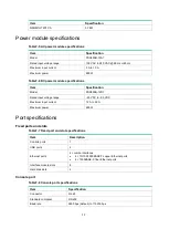
Страница 48: ... 0 54 kg 1 19 lb NSQM1GT8A 19 8 189 212 4 mm 0 78 7 44 8 36 in 0 55 kg 1 21 lb NSQM1GP8A 19 8 189 212 4 mm 0 78 7 44 8 36 in 0 55 kg 1 21 lb NSQM1GT4PFCA 19 8 189 212 4 mm 0 78 7 44 8 36 in 0 6 kg 1 32 lb Memory and storage media Table7 3 Memory and storage media specifications Item Specification Flash 8 MB Nor Flash 4 GB EMMC Flash Memory L5030 16 GB DDR3 L5060 32 GB DDR3 L5080 L5000 E 64 GB DDR3...

Страница 49: ...12D1 Rated input voltage range 40 VDC to 60 VDC Maximum input current 12 A to 22 A Maximum power 650 W Port specifications Fixed ports and slots Table7 7 Fixed port and slot specifications Item Description Console ports 1 USB ports 2 Ethernet ports 4 combo interfaces 4 10 100 1000BASE T copper Ethernet ports 4 1000BASE X fiber Ethernet ports Interface module slots 8 Hard disk slots 2 Console port ...

Страница 50: ...ification Connector RJ 45 Standard compliance 802 3 802 3u and 802 3ab Interface type MDI MDI X autosensing Cable type Category 5 or higher twisted pair cable Transmission distance 100 m 328 08 ft Interface speed and duplex mode 10 Mbps half full duplex 100 Mbps half full duplex 1000 Mbps full duplex NOTE The media dependent interface MDI standard is typically used on the Ethernet port of network ...

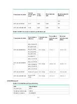
Страница 51: ... 125 500 SFP GE LH40 SM1310 1310 SMF 9 125 N A SFP GE LH40 SM1550 1550 SMF 9 125 N A SFP GE LH80 SM1550 1550 SMF 9 125 N A SFP GE LH100 SM1550 1550 SMF 9 125 N A Table7 13 1000BASE X SFP transceiver module specifications 2 Transceiver module Transmission distance Transmitted optical power dBm Received optical power dBm SFP GE SX MM850 A 550 m 1804 46 ft 9 5 to 0 17 to 3 500 m 1640 42 ft 275 m 902 ...

Страница 52: ...m 62 14 miles 0 to 5 30 to 9 10 GE fiber port Table7 14 10 GE fiber port specifications Item Specification Connector type LC Transceiver module type SFP Standard compliance 10GBASE R Interface speed LAN PHY 10 Gbps Table7 15 SFP transceiver module specifications 1 Transceiver module Central wavelength nm Fiber mode Fiber diameter µm Mode bandwidth MHz km SFP XG SX MM850 A 850 MMF 50 125 2000 500 4...

Страница 53: ... MM850 A 300 m 984 25 ft 10 31 Gbps 7 3 to 1 9 9 to 0 5 82 m 269 03 ft 66 m 216 54 ft 33 m 108 27 ft 26 m 85 30 ft 8 m 26 25 ft SFP XG LX220 MM131 0 220 m 721 78 ft 10 31 Gbps 6 5 to 0 5 6 5 to 1 5 220 m 721 78 ft 100 m 328 08 ft 220 m 721 78 ft 220 m 721 78 ft SFP XG LX SM1310 10 km 6 21 miles 10 31 Gbps 8 2 to 0 5 14 4 to 0 5 SFP XG LH40 SM1550 40 km 24 85 miles 10 31 Gbps 4 7 to 4 15 8 to 1 40 ...

Страница 54: ... for the QSFP 40G LR4 WDM1300 transceiver module Table7 18 QSFP transceiver module specifications Item Specification Central wavelength nm Four lanes 1271 1291 1311 1331 Fiber mode SMF Fiber diameter µm 9 125 Mode bandwidth MHz km N A Transmission distance 10 km 6 21 miles Transmission speed 40 Gbps Transmitted optical power dBm 7 to 2 3 Received optical power dBm 13 7 to 2 3 ...

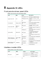
Страница 55: ...d HD1 Flashing green Data is being written in or read from the hard disk Steady green The hard disk has finished the initialization and is operating correctly Off The hard disk is not present or has failed Ethernet copper port LED combo interface 10 100 1000BA SE T Flashing green The port is receiving or sending data Steady green A link is present Off No link is present Ethernet fiber port LED com...

Страница 56: ...00BASE X Flashing green The port is receiving or sending data at 1000 Mbps Steady green A 1000 Mbps link is present Off No link is present 10GBASE R Flashing green The port is receiving or sending data at 10 Gbps Steady green A 10 Gbps link is present Off No link is present 40GBASE R Flashing green The port is receiving or sending data at 40 Gbps Steady green A 40 Gbps link is present Off No link ...

Страница 57: ...ulated copper wires twisted together Every wire uses a different color and has a diameter of about 1 mm 0 04 in A pair of twisted copper cables can cancel the electromagnetic radiation of each other and reduce interference of external sources An Ethernet twisted pair cable mainly transmits analog signals and is advantageous in transmitting data over shorter distances It is the commonly used transm...

Страница 58: ...ve although they provide better EMI prevention performance than UTPs so in most LANs UTPs are commonly used An Ethernet twisted pair cable connects network devices through the RJ 45 connectors at the two ends Figure9 2 shows the pinouts of an RJ 45 connector Figure9 2 RJ 45 connector pinout NOTE The RJ 45 Ethernet ports of the device use category 5 or higher Ethernet twisted pair cables for connec...

Страница 59: ... Pin 10Base T 100Base TX 1000Base T Signal Function Signal Function 1 Tx Sends data BIDA Bi directional data cable A Straight through cable white orange orange white green blue white blue green white brown brown 1 2 3 4 5 6 7 8 white orange orange white green blue white blue green white brown brown 1 2 3 4 5 6 7 8 Crossover cable white orange orange white green green white orange orange white gree...

Страница 60: ...l data cable C To ensure normal communication the pins for sending data on one port must correspond to the pins for receiving data on the peer port When both ports on the two devices are MDI or MDIX use a crossover Ethernet cable when one port is MDI and the other is MDIX use a straight through Ethernet cable To summarize straight through and crossover cables connect the following devices Straight...

Страница 61: ...ht source and transmission distance Uses lasers as the light source often within campus backbones for distance of several thousand meters Uses LEDs as the light source often within LANs or distances of a couple hundred meters within a campus network Table9 6 Allowed maximum tensile force and crush load Period of force Tensile load N Crush load N mm Short period 150 500 Long term 80 100 Fiber conne...

Страница 62: ...ohol to clean the end face of the two fiber connectors You can brush the end faces only in one direction Never bend or curve a fiber If the fiber has to pass through a metallic board hole or bend along the acute side of mechanical parts the fiber must wear jackets or cushions ...

Отзывы: