2-2
As shown in
, the device provides a primary grounding point at the rear panel and an
auxiliary grounding point at the left side. The primary grounding point has a grounding sign and a
grounding screw.
The grounding screw at the primary grounding point is also applicable to the auxiliary grounding
point. To use the auxiliary grounding point, attach the grounding cable to the grounding point before
you install the device in a rack.
The procedure is the same for connecting a grounding cable to the primary grounding point and the
auxiliary grounding point. This section uses the primary grounding point as an example.
To connect the grounding cable:
1.
Remove the grounding screw from the primary grounding point at the device rear.
2.
Attach the grounding screw to the ring terminal of the grounding cable.
3.
Use a screwdriver to fasten the grounding screw into the grounding hole.
4.
Connect the other end of the grounding cable to the grounding strip on the rack.
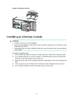
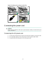
Figure2-1 Grounding the device by using the primary grounding point
Installing the device in a standard 19-inch rack
WARNING!
To avoid bodily injury and device damage, a minimum of two persons are required to install the
device.
CAUTION:
•
Ensure a clearance of 1 RU (44.45 mm, or 1.75 in) between the device and walls or other devices
for heat dissipation.
•
The mounting brackets and chassis rails are required to support the weight of the chassis.
To install the device in a standard 19-inch rack, make sure the rack meets the requirements
described in
Table2-2 Device dimensions and rack requirements
Device dimensions
Rack requirements
•
Height
—88.1 mm (3.47 in)
•
Width
—440 mm (17.32 in)
•
Total depth
—775.5 mm (30.53 in)
660 mm (25.98 in) for the chassis
90 mm (3.54 in) for the cable
•
A minimum of 1 m (3.28 ft) in depth
(recommended).
•
A minimum of 100 mm (3.94 in) between the front
rack posts and the front door.
•
A minimum of 760 mm (29.92 in) between the


