


63
The output shows that all fans of the switch operate properly.
•
In IRF mode:
<Sysname> display fan
Chassis 1:
Fan 1 State: Normal
Fan 2 State: Absent
The output shows that the fan in tray 1 operates properly, and no fan is in tray 2 on member switch
1.
You can configure either of the following automatic speed adjustment modes for fans as required:
•
Low temperature mode
—The fans operate at a high speed to ensure low temperature for the switch.
•
Silent mode
—The fans operate at a low speed with low noise, but the temperature is a little higher
than that in lower temperature mode. This mode is suitable for a noise-sensitive environment.
To configure the automatic speed adjustment mode:
Task Command
Remarks
Configure the automatic
speed adjustment mode
•
In standalone mode:
fan auto-control-mode
{
low-temperature-mode
|
silence-mode
}
•
In IRF mode:
fan auto-control-mode
{
low-temperature-mode
|
silence-mode
}
chassis
chassis-number
Use either command.
Available in system view.
By default, the switch
operates in low temperature
mode.
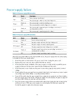
Displaying alarms present on a card
Use the
display alarm
command to display the alarms present on a card.
•
In standalone mode:
<Sysname> display alarm
Slot Level Info
6 ERROR The board in slot 10 is faulty.
•
In IRF mode:
<Sysname> display alarm
Chassis Slot Level Info
1 6 ERROR The board in slot 10 is faulty.
Table 18
Command output
Field Description
Level
Alarm severity. Possible values include ERROR, WARNING, NOTICE, and
INFO, in the descending order.
Info
Detailed alarm information.
Содержание S9500E Series
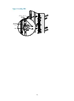
Страница 64: ...54 Figure 52 Installing FMTs ...
Страница 97: ...87 NOTE Remove the fibers if any from the SFP transceiver module before installing it ...
Страница 148: ...138 Figure 85 Example of a device label ...
Страница 151: ...141 Cable management examples Figure 89 Network cable management ...


