


115
Combo interface LED
The following LPUs provide combo interfaces. Each copper or fiber combo interface has a LED.
•
LSR2GT24LEB1
•
LSR1GT24LEC1
•
LSR2GP24LEB1
•
LSR1GP24LEC1
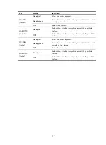
Table 49
Combo interface LED description
LED Status Description
LINK/ACT
(orange-green)
Steady orange
The combo interface is activated. By default, the copper
combo interface is activated.
Off
The combo interface is not activated.
Steady green
A link is present.
Off
No link is present.
Flashing green
Data is being transmitted and/or received on the combo
interface.
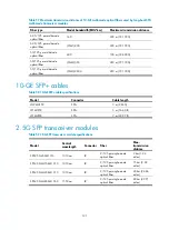
Base card LED
Table 50
Base card LED description
LED Status
Description
RUN (green)
Steady on
The card is faulty.
Off
The card is faulty or not in position.
Flashing
The card is operating properly.
Fast flashing
The LED flashes fast when the card is starting up. If the LED
keeps flashing fast, it indicates that the card is not
successfully registered.
NOTE:
The description of the base card LED on the LSR1LN1BNL1 and LSR1LN2BNL1 is the same.
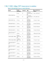
Subcard LEDs
LSR1DRUP1L1
Table 51
LED description
LED Status Description
MATESYNC Steady
on
The local Mate interface is synchronous with the peer Mate
interface.
Содержание S9500E Series
Страница 64: ...54 Figure 52 Installing FMTs ...
Страница 97: ...87 NOTE Remove the fibers if any from the SFP transceiver module before installing it ...
Страница 148: ...138 Figure 85 Example of a device label ...
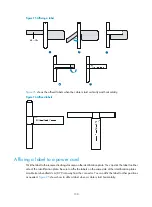
Страница 151: ...141 Cable management examples Figure 89 Network cable management ...


