


7
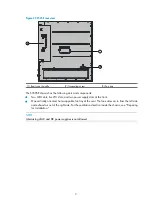
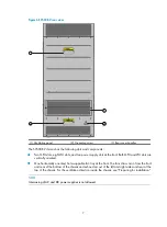
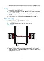
Figure 6
S9508E-V rear view
(1) Ventilation panel
(2) Grounding screw
(3) Rear cover handles
The S9508E-V chassis has the following slots and components:
•
Two MPU slots, eight LPU slots, and two power supply slots at the front. Both MPU and LPU slots are
vertically oriented.
•
One horizontally oriented, hot swappable fan tray at the front. The fans draw air in from the front
and rear of the bottom of the chassis and exhaust air out of the left and right sides and rear at the
top of the chassis. For the ventilation direction inside the chassis, see "Preparing for installation."
NOTE:
Intermixing of AC and DC power supplies is not allowed.
Содержание S9500E Series
Страница 64: ...54 Figure 52 Installing FMTs ...
Страница 97: ...87 NOTE Remove the fibers if any from the SFP transceiver module before installing it ...
Страница 148: ...138 Figure 85 Example of a device label ...
Страница 151: ...141 Cable management examples Figure 89 Network cable management ...


