Installation Manual
H3C S5500-SI Complete Series Ethernet Switches
Chapter 3 Installing the Switch
3-13
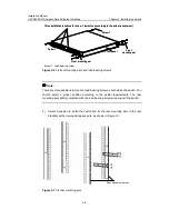
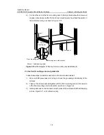
(2)
(1)
(1): Air filter
(2): Fastening screw
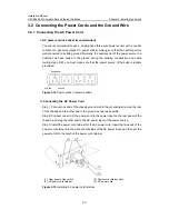
Figure 3-17
12V-RPS power socket for the Ethernet switch
z
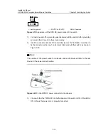
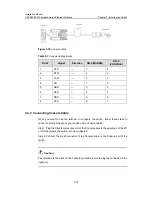
Connect one connector (in A direction) of the 12V-RPS DC power cable (Figure
3-18 shows a recommended 12V-RPS DC power cable) to the RPS DC power
socket of the switch, and the other connector (in B direction) to the corresponding
12 V power output socket of the RPS power module.
1
7
8
14
14
8
7
1
Direction A
Direction B
Figure 3-18
12V-RPS DC power cable
z
Connect one end of the delivered AC power cable to the power socket of the RPS
power module and the other end to the socket of an external AC power supply.
Step 3: Check whether the PWR LED on the front panel of the switch is ON. If yes, the
power is properly connected.
Caution:
z
Make sure that the ground wire has been properly connected before powering on
the switch.
z
You can use only the 12V-RPS DC power cord recommended by H3C.
II. Connecting the DC Power Cord of the S5500-28C-PWR-SI and
S5500-52C-PWR-SI switches
The S5500-28C-PWR-SI and S5500-52C-PWR-SI switches use RPS DC power,
whose rated input voltage is in the range of -52V to -55V.


