ELECTRO FREEZE Shake Model CS704
185260
32
11.2 Syrup Line Assembly And Sanitizing
Important:
The chocolate syrup is a different
viscosity and requires different
hoses. Always be aware of this when
assembling.
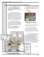
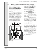
1. Place a silicone bead of a
lubricant [i.e. Dow Corning Compound 7,
HC158066] on the outside of each pump
peristaltic tube. Wrap the
peristaltic
tube
around the pump head centering it on
the rollers. Place the head in the housing
making sure the white plastic coupling is
outside of the housing and the black tie
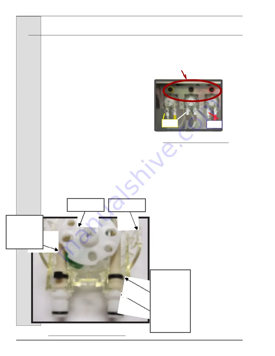
wrap is inside as shown in figure 11-4.
2. Open the cabinet below the
freezer to install the pump housings. The
pump housing with the clear
peristaltic
tube is to be used on the pump with the
brown colored potentiometer dial (see
figure 11-5).
Important:
The clear larger hose is to be used
only for the chocolate syrup.
Line up the center of the pump head to fit
into the pump drive housing mounted on
the cabinet back wall, turn until it snaps
into place.
3.
Place the three (3) remaining pump heads
on the mix pumps in the cabinet.
4. Connect the syrup lines from
the freezer to the pumps. The color
coded hoses need to be matched to
the corresponding color coded on the
potentiometer dials above the mix pumps.
5. Sanitize the syrup line system.
a.
Prepare 2 gallons (7.6 liters)
of sanitizing solution in a container.
Sanitizing solution must be mixed
according to manufacturer’s instructions
to yield 100 PPM strength chlorine
solution. (example: Stera-Sheen Green
Label). Use warm water (100-110°F or
37-43°C) to wash, rinse, and sanitize.
Fill
a clean empty bucket with 2 gallons of
sanitizing solution.
—continued
Figure 11-4 Syrup Pump Housing
Proper Hose
Installation
Note position of
the black tie wrap
in the housing
and the white
plastic coupling
below the
housing
Pump
Peristalic Tube
Must be
lubricated when
installing.
Pump Head
Pump Housing
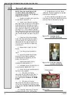
Figure 11-5
Potentiometers
CLIP
CLIP
Содержание Arby's Electro Freeze Compact Series
Страница 2: ......
Страница 7: ...ELECTRO FREEZE Shake Model CS704 Safety Decal Locations v 1 P N HC165126 2 P N HC165025...
Страница 10: ......
Страница 15: ...ELECTRO FREEZE Shake Model CS704 185260 5 3 5 Dimensions Figure 3 2 Electro Freeze Model CS704 Dimensions...
Страница 16: ...ELECTRO FREEZE Shake Model CS704 185260 6 4 Part Names and Functions Figure 4 1 Head Assembly 19 20...
Страница 24: ...ELECTRO FREEZE Shake Model CS704 185260 14 Figure 6 2 Dispense Head Assembly 6 2 Disassembly Instructions...
Страница 30: ...ELECTRO FREEZE Shake Model CS704 185260 20 Figure 7 4 Head Assembly 7 Assembly continued...
Страница 53: ......
Страница 55: ......
Страница 65: ...ELECTRO FREEZE Shake Model CS704 185260 10 Figure 8 Panel View Sheet 1 of 2...
Страница 67: ...ELECTRO FREEZE Shake Model CS704 185260 12 Figure 9 Side View Sheet 1 of 2...
Страница 71: ...ELECTRO FREEZE Shake Model CS704 185260 16 ELECTRO FREEZE Shake Model CS704 16...

