ELECTRO FREEZE Shake Model CS704
185260
24
Priming the freezer removes all excess
air and sanitizer from the freezing cylinder
and sets the proper overrun for the first
cylinder of product. Always have clean,
sanitized hands when handling mix feed
assemblies. Handle only the top 1”. Make
sure the mix feet tube assembly and the
inside of the hopper cover are cleaned
with sanitizer.
1. Wash and sanitize your hands
and forearms.
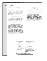
2. Place an empty container under
the dispense head. Install the mix feed
tube assembly in the closed position,
as shown in figure 8-2, into the mix feed
drain in the hopper. Pour a minimum of
2-1/2 gallons of mix into the hopper.
3. Hold the plunger open and
remove the mix feed tube to allow mix to
push out the sanitizer. When pure mix
flows from the dispense head close the
plunger.
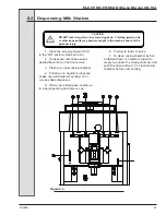
4. When the mix stops bubbling
install the mix feed tube into the mix feed
hopper drain in the “open” position. Place
the selector switch to the “AUTO” position
and the syrup switch to the “ON” position.
Important:
Failure to completely remove sanitizer
or water from the freezing cylinder
before placing in “AUTO” will damage
the freezer.
5. Fill the hopper with mix and Install
the hopper cover.
6. During long idle periods, the
regulator should be closed —
but
remember — when dispensing product,
ensure that the mix feed regulator is
“OPEN” at all times.
If not open, the flow
of mix will be restricted. If lubricant blocks
the inlet hole in the tube it would also
restrict the flow of mix.
8.2 Priming
Pin is not in line with hole.
Look through top hole in
tube — you should see the
inner white plastic insert
tube (regulator) blocking the
opening.
Look through top hole
in tube — you should
see clear through.
Pin is in line with hole.
Figure 8-2 Mix Feed Tube Positions
Содержание Arby's Electro Freeze Compact Series
Страница 2: ......
Страница 7: ...ELECTRO FREEZE Shake Model CS704 Safety Decal Locations v 1 P N HC165126 2 P N HC165025...
Страница 10: ......
Страница 15: ...ELECTRO FREEZE Shake Model CS704 185260 5 3 5 Dimensions Figure 3 2 Electro Freeze Model CS704 Dimensions...
Страница 16: ...ELECTRO FREEZE Shake Model CS704 185260 6 4 Part Names and Functions Figure 4 1 Head Assembly 19 20...
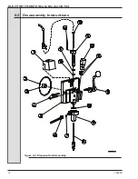
Страница 24: ...ELECTRO FREEZE Shake Model CS704 185260 14 Figure 6 2 Dispense Head Assembly 6 2 Disassembly Instructions...
Страница 30: ...ELECTRO FREEZE Shake Model CS704 185260 20 Figure 7 4 Head Assembly 7 Assembly continued...
Страница 53: ......
Страница 55: ......
Страница 65: ...ELECTRO FREEZE Shake Model CS704 185260 10 Figure 8 Panel View Sheet 1 of 2...
Страница 67: ...ELECTRO FREEZE Shake Model CS704 185260 12 Figure 9 Side View Sheet 1 of 2...
Страница 71: ...ELECTRO FREEZE Shake Model CS704 185260 16 ELECTRO FREEZE Shake Model CS704 16...

