14
GX8.0 CROSSTRAINER
STEP 11. Computer Installation
Remove four M5x10 Bolts (14) from the back
of the Computer (13).
Connect the Sensor Wire (21) and Hand Pulse
Sensor Wires (17) to the wires that come
from the Computer (13) and then attach the
Computer (13) onto the top end of the Front
Post (2) with four M5x10 Bolts (14) that were
removed.
Please note: coat the Aluminum Rod with
PTFE Lubric.
STEP 12. AC Adapter Installation
Plug one end of the AC Adapter(104) into the
power jack of the Power Supply Wire(106) onto
the back of the Left Shroud. Before plugging in,
make sure to check carefully the specifications
on the Adapter. Plug the other end of the AC
Adapter(104)into the electrical wall outlet.
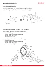
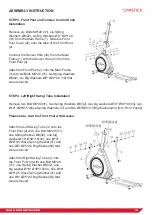
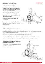
ASSEMBLY INSTRUCTION
Содержание GX8.0
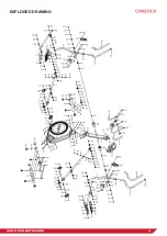
Страница 4: ...4 GX8 0 CROSSTRAINER EXPLODED DRAWING ...
Страница 5: ...5 GX8 0 CROSSTRAINER EXPLODED DRAWING ...
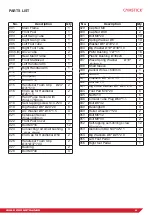
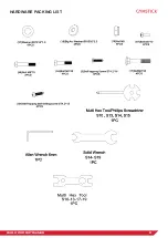
Страница 8: ...8 GX8 0 CROSSTRAINER HARDWARE PACKING LIST ...


