background image

Installation | Mounting a lens

2-3

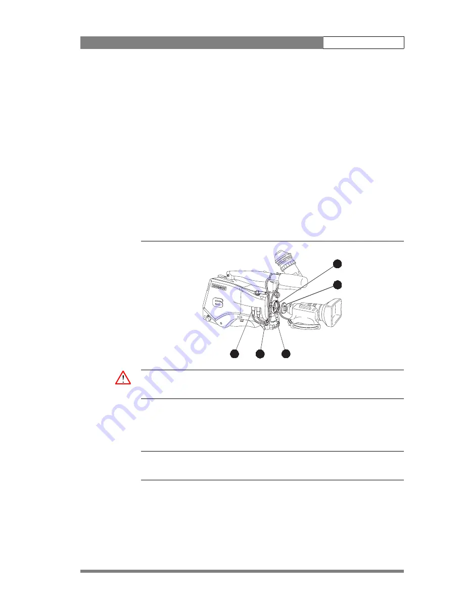
2.3  Mounting a lens

To attach a lens to the camera head proceed as follows:

1.

Ensure that the lens locking ring (1) is in the unlocked position - turned 
counterclockwise.

2.

Remove the dust protection cap (2).

3.

Slot the lens into the lens mount (3).

4.

Turn the lens locking ring (1) clockwise to lock the lens in place.

5.

Connect the lens cable to the lens connector (4) at the right side of the 
camera.

6.

Place the lens cable into the bottom clip at the front of the camera and clip (5) 
located at the side. (Pull and twist clip to open it.)

Figure 2-2.  Lens mounting

bts1009

4

5

3

2

1

Caution 

Do not attach a lens weighing more than 5 kg to the camera without a support.

When a new lens is fitted to the camera it may be necessary to carry out some 
adjustments to optimize its use, for example, back focus or shading. For more 
information about these adjustments refer to the lens manufacturer’s documentation

Note


Always mount the dust protection cap when the lens is not connected to the camera.

Содержание LDK 400

Страница 1: ...User s Guide LDK 400 CAMERA SYSTEM 3922 496 30531 version 1 ...

Страница 2: ...use interference in which case the user at his own expense will be required to take whatever measures may be required to correct the interference Copyright Für diese Unterlage behalten wir uns alle Rechte vor Gemäß DIN 34 Technische Änderungen im Zuge der Weiterentwicklung vorbehalten Copying of this document and giving it to others and the use or communication of the contents thereof are forbidde...

Страница 3: ...older 2 4 Positioning the viewfinder 2 5 1 5 inch Viewfinder Accessories 2 5 Wide angle eyepiece 2 5 Left eye adapter 2 6 Mounting a microphone 2 7 Tripod adapter plate 2 8 Adjusting the shoulder pad 2 9 Mounting a top light 2 10 Zoom controls 2 11 Attaching an adapter 2 12 Chapter 3 Cabling and connectors Configurations 3 2 Camera with Triax adapter 3 2 Multiple Triax cameras with C2IP network 3 ...

Страница 4: ...Auxiliary connector 3 14 Chapter 4 Operating instructions Camera head controls 4 3 Viewfinder controls 4 4 Assigning functions to buttons 4 5 Using the camera 4 6 Switching on the power 4 6 Controlling the camera 4 6 Access and Security 4 7 Camera cards 4 7 Access control 4 8 Camera card slot 4 8 System Menu 4 9 Entering the System menu 4 9 Finding your way 4 10 Leaving the System Menu 4 10 Making...

Страница 5: ...uto skin contour 4 21 Classic mode 4 23 Managing files 4 24 Scene files 4 24 Operator files 4 24 Standard files 4 25 Customer standard files 4 25 User levels 4 26 Selecting the user level 4 26 Smart Touch 4 27 Triax adapter controls 4 28 Powering the camera 4 29 Selecting monitoring signals 4 29 Using audio 4 29 Intercom 4 30 Communication 4 31 Chapter 5 Menu structure Menu structure 5 2 Main top ...

Страница 6: ...LDK 400 User s Guide vi ...

Страница 7: ...red against any unintended operation The appropriate servicing authority must then be informed For example safety is likely to be impaired if the apparatus fails to perform the intended function or shows visible damage Any changes or modifications not expressly approved in this manual could void your authority to operate this equipment Cautions and Warnings Read and comply with the warning and cau...

Страница 8: ...onnected to protective earth Do not interrupt the protection conductor inside or outside the unit Do not disconnect the protective earth terminal Intentional interruption is prohibited and is likely to make the unit dangerous To prevent risk of overheating ventilate the units correctly For safety reasons the Base Station must be mounted in a 19 inch rack which has safety covers according to IEC65 ...

Страница 9: ...lt in biological hazard if used according to the instructions Laser safety statement US Fibre optic transmission units are classified as a CLASS 1 Laser Product according to 21CFR 1040 10 of the US Food and Drug Administration FDA Center for Devices and Radiological Health WARNING Use of controls adjustments or performance of procedures other than those specified herein may result in hazardous rad...

Страница 10: ...als in your plug proceed as follows The wire coloured GREEN AND YELLOW must be connected to the terminal on the plug marked with the letter E or by the safety earth symbol or coloured GREEN or GREEN AND YELLOW The wire coloured BROWN must be connected to the terminal marked with the letter L or coloured RED The wire coloured BLUE must be connected to the terminal marked with the letter N or colour...

Страница 11: ...nces for extended periods Do not allow sunlight to shine into the viewfinder Do not allow LASER beams to shine into the lens as this could damage the CCD sensors Avoid extreme highlights as these can cause various kinds of optical reflections Be careful when connecting and disconnecting triax cables Do not mix triax units from different types of camera systems HD with SD RGB triax with digital tri...

Страница 12: ...ld not be broken If required the central earth connection wire of the studio can be connected to terminal PE Only if the studio or OB van is equipped with separate protective and video earth systems may the metal strap be removed Under these circumstances the video earth terminal must be connected to the central functional earth potential video earth of the studio This earth potential should have ...

Страница 13: ...that is equally at home in the studio or out on location in an OB environment 1 1 1 Frame Transfer DPM sensor The Frame Transfer CCD DPM sensor offers superior performance and can handle highlights of up to 600 The 2 3 inch sensors have a high dynamic range and high linear sensitivity over all camera lens apertures Frame Transfer technology ensures that there is no lag nor smear The Frame Transfer...

Страница 14: ... together with hard contrast and saturated colour in bright scenes The matrix and gamma sequence is software programmable for precise colour matching 1 1 3 Film like characteristics The pivoting knee circuit adapts both the knee point and the compression ratio according to the highlight content of the picture to emulate the softly limiting S shaped transfer characteristics of film Digital True Col...

Страница 15: ...rolled effect filter wheel some versions only Electronic colour filter for creating a special look warm cold for a scene or for a smooth colour temperature control around the white balance setting Camera card for personal settings and security Owner s card for setting user levels and for copying and storing control settings Protected easy to operate controls and switches with read out of all setti...

Страница 16: ...quantization 14 bit A to D Digital signal processing 18 MHz and 36 MHz 24 bit accuracy Sensitivity 2000 lux at F9 0 reflectance 90 Minimum illumination Approx 2 lux at F 1 4 and 30 dB gain Exposure control Down to 1 1000 Clean scanning NTSC between 61 1 and 151 0 Hz PAL between 51 0 and 103 0 Hz Optical system F1 4 with quartz filter Optical filters Clear 1 4 ND 1 16 ND 1 64 ND Clear 4 point star ...

Страница 17: ... processing 18 MHz and 36 MHz 24 bit accuracy Sensitivity 2000 lux at F14 0 reflectance 90 Minimum illumination Approx 0 15 lux with F1 4 lens and 42 dB gain Exposure control Down to 1 2000 Clean scanning NTSC between 61 1 and 151 0 Hz PAL between 51 0 and 103 0 Hz Optical system F1 4 with quartz filter Optical filters Clear 1 4 ND 1 16 ND 1 64 ND Clear 4 point star 6 point star soft focus optiona...

Страница 18: ... 3000m with RGB long triax modification optional Intercom XLR5 Tuchel with channels ENG PROD PROG Video CVBS out Optional 1 Vpp 75 Ohm BNC Video telepromter out 1 Vpp 75 Ohm BNC not for LDK 5400 Monitor Y 1 Vpp 75 Ohm BNC Reference in 1 Vpp 75 Ohm BNC not for LDK 5400 Tracker 11 pins Communication Signalling not for LDK 5400 Auxilary Data 11 pins private data not for LDK 5400 Rear microphone in XL...

Страница 19: ...Introduction Specifications 1 7 1 3 1 Dimensions Figure 1 1 Dimensions ...

Страница 20: ...et dynamic XLR 5 double muff LDK 8111 37 Headset dynamic XLR 5 single muff LDK 8111 51 Scriptboard with light LDK 6985 21 Transport flightcase LDK 5020 00 Carrying bag LDK 5020 01 Camera light 20W LDK 5950 00 AC power supply LDK 4377 40 Camera IR remote control LDK 5200 00 Zoombox for Angenieux lenses LDK 6113 16 Zoomcontrol for Canon lenses LDK 6113 26 Zoombox for Fujinon lenses LDK 6113 36 Camer...

Страница 21: ...11 2 1 Packing unpacking Inspect the shipping container for evidence of damage immediately after receipt If the shipping container or cushioning material is damaged it should be kept until the contents of the shipment have been checked for completeness and the units have been checked mechanically and electrically The shipping container should be placed upright and opened from the top Remove the cu...

Страница 22: ...ping container securely 5 Mark shipping container FRAGILE to ensure careful handling 2 2 Transport case It is important to protect your camera against damage when transporting it To do this a transport case LDK 5020 00 is optionally available for the camera lens viewfinder and some accessories Figure 2 1 Transport case Clear Clear A 1 Star 4P ND1 4 B 1 Star 6P ND 1 16 C 1 Soft focus ND 1 64 D 1 Do...

Страница 23: ...side of the camera 6 Place the lens cable into the bottom clip at the front of the camera and clip 5 located at the side Pull and twist clip to open it Figure 2 2 Lens mounting bts1009 4 5 3 2 1 Caution Do not attach a lens weighing more than 5 kg to the camera without a support When a new lens is fitted to the camera it may be necessary to carry out some adjustments to optimize its use for exampl...

Страница 24: ...urning it clockwise as seen from rear so that the viewfinder is mounted securely to the support 4 Connect the viewfinder cable to the viewfinder connector socket 6 at the top right of the camera 5 Slide the microphone holder 4 onto the viewfinder and secure with the knurled screw 5 Caution Always fit the microphone holder as it functions as a safety stop for the viewfinder 6 To improve the comfort...

Страница 25: ...itioned backwards and forwards along the camera axis Loosen the support bracket round bar retaining lever 2 and slide the round bar 3 forwards or backwards When the desired position is reached tighten the support bracket round bar retaining lever 2 again To use the viewfinder at a distance press the button 4 below or above the eyepiece tube and swing it free of the associated clip 5 The display ca...

Страница 26: ...iece 1 to the two clips 3 ensuring that they both click into place Figure 2 5 Viewfinder wide angle eyepiece 4 2 1 3 2 5 2 Left eye adapter A left eye adapter is optionally available LDK 5390 10 to allow the viewfinder to be used with the left eye Before mounting the viewfinder onto the camera attach the left eye adapter 1 to the viewfinder and secure it using the screw 2 Do not forget to mount th...

Страница 27: ...be 5 Close the holder and tighten the knurled screw at the top Don t allow the wind hood to touch the holder 7 as this reduces the damping effect 6 Connect the microphone cable to the MIC audio connector 3 on the right side of the camera To avoid mechanical pick up do not let the microphone cable touch the holder 7 Place the microphone cable into the top clip at the front of the camera and into cl...

Страница 28: ...he slot on the bottom of the camera engages the stud 2 at the rear of the tripod adapter plate 2 Firmly push the camera forward until it clicks into place Caution Failure to attach the camera to the tripod adapter plate in the correct manner could result in an unsecured camera Ensure that the rear stud 2 is engaged and that the camera clicks into place Remove the camera from the tripod as follows ...

Страница 29: ...n the camera is mounted on the tripod tighten this locking lever 5 to ensure that the stud 2 at the rear of the plate is locked firmly in place When removing the camera first open the locking lever 5 to free the rear stud 2 2 8 Adjusting the shoulder pad To change the position the shoulder pad press and hold lever 1 The shoulder pad can now be moved backwards and forwards along the axis of the cam...

Страница 30: ...crew the top light into either the WW1 4 20 screw hole 2 located on the carrying handle or the screw hole 3 on the top of the microphone holder 2 Power the top light according to the instructions delivered with the light Figure 2 10 Top light Clear Clear A 1 Star 4P ND1 4 B 2 Star 6P ND 1 16 C 3 Soft focus ND 1 64 D 4 2 1 3 1 ...

Страница 31: ...3 36 for Angenieux This control unit not only controls the zoom but also has mini button controls for the VTR start stop function and the VTR Ret function These are located under the front of the carrying handle 2 The instructions for mounting the zoom control unit and the function of the controls are supplied with the unit Figure 2 11 Zoom controls Clea r Clea r A 1 Star 4P ND 1 4 B 2 Star 6P ND ...

Страница 32: ...er to the camera proceed as follow 1 Using the rail 1 on the bottom of the camera head as a guide fit the guide pins 2 on either side of the connector and the guide pin 3 at the top rear of the camera head into the corresponding slots of the adapter 2 First tighten the two horizontal screws 4 on the top of camera 3 Next tighten the two horizontal screws 5 at the front of the camera 4 Lastly tighte...

Страница 33: ... connectors 3 5 Viewfinder connector 3 5 Lens connector 3 6 Audio microphone connector 3 6 RS232 serial connector 3 7 Triax adapter connectors 3 8 Triax connector 3 9 CVBS output connector 3 9 Viewfinder External video output connector 3 9 Script light power supply socket 3 10 Teleprompter video output connector 3 10 DC power and tally output socket 3 10 Audio microphone 2 connector 3 11 DC power ...

Страница 34: ...Camera head Triax adapter Triax cable Base Station Ethernet cable OCP 400 Power supply 3 1 2 Multiple Triax cameras with C2IP network Each camera head with an LDK 5430 Triax adapter can be connected to an LDK 4501 Base Station using a Triax cable The maximum length of cable that can be used without significant degradation of the video signal is 3000m 10 000 ft for a 14mm Triax cable The power supp...

Страница 35: ...t card Po we r on P we l Tracker Aux 1 2 3 4 A B C D Clear ND1 4 ND1 16 ND1 64 Clear Star 4P Star 6P Soft Focus Smart card Po we r on P we l Tracker Aux 1 2 3 4 A B C D Clear ND1 4 ND1 16 ND1 64 Clear Star 4P Star 6P Soft Focus Smart card Po we r on P we l Tracker Aux 1 2 3 4 A B C D Camera head Triax adapter Base Station Triax cable Ethernet cable Hub or switch Series 9000 OCP Hub or switch MCP 4...

Страница 36: ...he SuperXpander The SuperXpander is connected to an LDK 4501 Base Station using a Triax cable The maximum length of cable that can be used without significant degradation of the video signal is 3000m 10 000 ft for a 14mm Triax cable The Base Station is powered by a separate mains power supply An OCP 400 operational control panel can be connected directly to the Base Station using a cross over Ethe...

Страница 37: ...finder connector Figure 3 5 Camera viewfinder connector 3 4 1 2 5 8 9 6 7 10 13 14 11 12 15 18 19 16 17 20 1 80V 2 n c 3 GND 4 INTN D 5 vf ext video 6 n c 7 vf video ret 8 SDA D 9 SCL D 10 vf ext video ret 11 GND 12 vf video 13 Pb vf ret 14 Pr vf ret 15 GND 16 batt 17 batt 18 Pb vf 19 Pr vf 20 shield 20 pole female panel view Panel part number X14 5322 214 12544 Cable part number male 5322 320 121...

Страница 38: ...Focus follow 12 Spare not standard on lens Hirose 12 pole female panel view Panel part number X15 5322 265 10389 Cable part number male 5322 265 41208 3 2 3 Audio microphone connector Figure 3 7 Audio microphone connector 3 1 2 1 Audio Screen 2 Audio In 3 Audio Return Microphone impedance 200 ohm Sensitivity range 70 to 28 dBm Signal at pin 2 of audio input is in phase with signal at pin 2 of audi...

Страница 39: ...ectors Camera connectors 3 7 3 2 4 RS232 serial connector Figure 3 8 RS232 serial connector 5 4 3 2 1 9 8 7 6 1 SPARE 2 RS RXD 3 RS TXD 4 RS DTR 5 RS DGND 6 RS DSR 7 RS RTS 8 RS CTS 9 12V SubD 9 pin male panel view X12 ...

Страница 40: ...TP Mic 2 48V On 12V 1 5A DC Out Ext 2 Ext 1 REF IN Aux Tracker Triax connector CVBS output Viewfinder Ext video output Script light power supply Teleprompter output not for LDK 5400 DC power and tally output not for LDK 5400 Intercom headset Audio microphone 1 input DC power supply input Audio microphone 2 input not for LDK 5400 Reference signal input not for LDK 5400 Tracker communication connect...

Страница 41: ... X100 3 3 2 CVBS output connector Figure 3 11 CVBS output connector This socket provides a 1 0 Vpp CVBS output video signal if the optional encoder board is fitted BNC connector panel view X105 3 3 3 Viewfinder External video output connector Figure 3 12 Viewfinder External video output connector This socket provides a 1 0 Vpp VBS output viewfinder signal or the external video signal from the Base...

Страница 42: ...ket supplies the 1Vpp teleprompter signal applied to the Base Station This socket has no output if the reference input socket is used as a return video channel BNC connector panel view X112 3 3 6 DC power and tally output socket Figure 3 15 DC power and tally output connector 4 1 2 3 1 Ground 2 On air 3 No connection 4 12 Vdc max 18W Shield of cable directly to the connector housing The socket pro...

Страница 43: ...nge 64 to 24 dBu Signal at pin 2 of audio input is in phase with signal at pin 2 of audio output XLR 3 pole female panel view X107 3 3 8 DC power input socket Caution The input voltage must not exceed 17 Vdc Figure 3 17 DC power input connector 4 1 2 3 1 Ground 2 No connection 3 No connection 4 10 5 Vdc 17 Vdc This socket accepts a DC voltage of 12V nominal Maximum power consumption 23W XLR 4 pin ...

Страница 44: ...dset connector 4 1 2 3 5 1 Microphone return 2 Microphone 3 Telephone return 4 Telephone left 5 Telephone right Microphone level 64 dBu 24 dBu switchable Microphone impedance 600 Ohm Telephone level 6 dBu nominal Telephone output impedance 50 Ohm XLR 5 pole female panel view X104 Figure 3 20 Tuchel intercom headset connector 4 1 2 3 5 6 1 Telephone left 2 Not connected 3 Microphone 4 Microphone re...

Страница 45: ...on of this socket in the camera Install menu or the Base Station System menu BNC connector panel view X111 3 3 12 Tracker communications connector Figure 3 22 Tracker communications connector 4 1 2 3 5 6 7 8 9 10 11 1 On air signal return 2 Tracker microphone return 3 Tracker microphone input 4 Production tracker 5 Sidetone engineering tracker 6 Intercom return 7 Program sound tracker 8 Cameraman ...

Страница 46: ...n 8 Ground 9 Private Data Base Station Camera 10 Ground 11 Shield Private data input signals 0 0 8 Volt 1 2 4 Volt max level 12 Volt input impedance 100 kOhm baud rate 2400 bits s nom 4800 bits s max Private data output signals C MOS levels 5V output impedance 1 kOhm Analogue outputs AN0 and AN1 output level 0 5 Volt output impedance 100 Ohm Fischer 11 pole female panel view Panel part number X109...

Страница 47: ...ccess control 4 8 Camera card slot 4 8 System Menu 4 9 Entering the System menu 4 9 Finding your way 4 10 Leaving the System Menu 4 10 Making changes 4 11 Undoing changes 4 11 Viewfinder preferences 4 12 Viewfinder picture quality 4 12 Video level indication 4 12 Tally indicators 4 12 Viewfinder markers 4 12 Lens preferences 4 13 Lens type 4 13 Auto iris 4 13 Extended Iris 4 13 Lens indicators 4 1...

Страница 48: ...s 4 24 Operator files 4 24 Standard files 4 25 Customer standard files 4 25 User levels 4 26 Selecting the user level 4 26 Smart Touch 4 27 Triax adapter controls 4 28 Powering the camera 4 29 Selecting monitoring signals 4 29 Using audio 4 29 Intercom 4 30 Communication 4 31 ...

Страница 49: ...15 16 17 18 19 2 1 Filter wheel switches 2 Filter wheel indicators 3 Camera card slot 4 SW1 VTR Save assignable button 1 5 SW2 Extended Iris assignable button 2 6 Standard scene file button Std 7 Black stretch switch 8 Colour temp switch White bal 9 Colour bars switch Bars 10 Gain selection switch 11 Power On Off switch 12 Menu rotary control 13 Menu select switch 14 Clean Scan button 15 White bal...

Страница 50: ... 37 38 21 35 20 Tally switch 21 Zebra switch 22 Option assignable switch 4 23 Brightness control 24 Contrast control 25 Crispening control 26 Dioptre 27 Tally indicators red 28 Gain indicators 29 Top indicators 30 Iris indication 31 Zebra pattern 32 Safe area marker 33 Non standard indicator 34 Colour temperature indicators 35 Message box 36 Centre marker 37 Cadre marker 38 Zoom indication ...

Страница 51: ...s can be assigned the following functions Table 4 1 Button Assignments Switch Assignment VTR Save 4 VTR Save Switch on external signal 1 Switch on external signal 2 Ext Iris 5 Extended Iris Switch on external signal 1 Switch on external signal 2 VTR Start 19 VTR Start Stop Switch on external signal 2 Intercom Option 22 on VF None Disable camera The function and behaviour momentary or alternating o...

Страница 52: ...the Power switch 11 of the camera to the ON position Note The BATT indicator in the viewfinder lights if the camera supply voltage is less than 11V 3 Allow a few moments for the camera to perform a self test and for the system to establish communications 4 3 2 Controlling the camera There are several ways of controlling the camera Using an OCP connected to the Base Station Using the switches on th...

Страница 53: ...operator files The owner s card is unique to every camera Owner s card and camera must have the same serial number An ownerís card is linked to the serial number of the camera and cannot be used as an ownerís card for another camera The user s card has two functions As a storage device for four scene files As a storage device for two operator files Scene files Both the user s card and the owner s ...

Страница 54: ...lect the Security menu without this card inserted you must enter the correct PIN code to gain access to this menu PIN code The PIN code of the camera can be viewed and changed in the Security menu The camera s PIN code when it leaves the factory is set to 0000 It is strongly advised that this code be changed by the owner on receipt of the camera This ensures added protection against unaurthorised ...

Страница 55: ...hat are listed in the main menu as follows Each of these menus gives you access to a particular group of functions Spend some time using the controls and menus to discover the various functions You will quickly learn to operate the camera intuitively Note Some of the menu items may not appear if the user level is not set to 3 4 5 1 Entering the System menu Press the Select button 13 after the came...

Страница 56: ... visible but are located above the first item Use the Rotary control to scroll up to them Select TOP to bring you back to the MAIN menu Select PREVIOUS to go back to the menu that you were in before the current one The LENS menu for example shows the items displayed when you first enter the menu The other items are available by scrolling up or down with the Rotary control Figure 4 6 Lens menu Lens...

Страница 57: ...available it cannot be changed This is indicated by three dashes This can occur for example when a function is switched off The analogue values associated with that function are then unavailable If there are only two values associated with the function then pressing the Select button 13 toggles between these two values If a value is displayed next to a function that is one of several possible valu...

Страница 58: ...ion works 4 6 3 Tally indicators The red Tally indicators 27 at the front of the viewfinder and at the rear of the carrying handle light to indicate that the camera is on air The Tally switch 20 is used to control the Tally indicator at the front of the viewfinder When this switch is set to the OFF position the Tally indicator does not light when the camera is on air The Tally switch does not cont...

Страница 59: ...atically regulates the video signal level by adjusting the iris opening the gain level and the exposure time to suit the ambient lighting conditions To switch on the extended iris function use the Extended iris button 5 at the left front side of the camera When this button is pressed once the current value of the automatic extended iris function is displayed Press the button twice in quick success...

Страница 60: ...or most video functions The table in the Appendix lists the values that are set when the standard file is recalled To recall the standard values for the various video functions press the green STD button 6 on the left front side of the camera and hold it for two seconds The standard values only take effect when the camera is not on air The standard file can be selected as either a factory or a cus...

Страница 61: ...n 0dB the Studio Mode is switched off However if you reset the gain to 0dB the Studio Mode value returns to its last set position 4 8 4 Gain selection Depending on the available light levels it may be necessary to adjust the gain of the camera The gain is selected via the up down scroll Gain switch 10 on the left front side of the camera When this switch is pressed initially the current value of t...

Страница 62: ...r optical filters to be able to white balance correctly The range of the auto white balance is so wide from 2 5K to 20K that there is never any need to use colour filters to obtain the correct white Rotate the switches to move the optical filter wheels The outer bigger filter switch has four positions The inner smaller filter switch also has four positions The status of the filter wheels is displa...

Страница 63: ...he electronic colour filter is reset to its default value Selecting the colour temperature The up down Colour temperature White bal switch 8 on the left front side of the camera allows a choice between Three preset colour temperatures 3200K 3 2K for studio lighting conditions 5600K 5 6K for outdoors clouded conditions 7500K 7 5K for outdoors clear blue skies Three memory positions FL memory positi...

Страница 64: ...ing appears in the viewfinder ND RE BATT TAPE REC AW2 AW1 FL 7 5 5 6 3 2 AWHITE window 3 Point the camera so that the reference white surface is between the two small white boxes 4 Press the White balance switch 15 again to start the measurement procedure A message indicating that the process is runnning appears ND RE BATT TAPE REC AW2 AW1 FL 7 5 5 6 3 2 AWHITE running 5 When the process is comple...

Страница 65: ...re speed lowers the camera sensitivity proportionally Selecting the exposure time The momentary up down Exposure time switch 16 gives a choice of exposure time settings Table 4 5 Exposure time values Value Function Nom nominal setting Var enables the exposure to be varied CRT for shooting sync locked monitors Film to vary the exposure with running shutter 1 200 for fast moving objects 1 500 for fa...

Страница 66: ...a higher frame frequency for example computer monitors use the Clean Scan facility Vertical shift V Shift Sometimes when shooting TV screens or monitors with the same display frequency as the camera for example TV sets a horizontal black bar is seen in the viewfinder because the camera is blanking while the TV is not The V Shift switch 18 shifts the camera blanking The V Shift switch 18 at the fro...

Страница 67: ...16 9 cameras To remove these disturbing line pairing effects between monitor and camera lines select the CRT option with the Exposure time switch 16 4 8 8 Black stretch The black stretch function gives more detail in the dark areas of the picture without effecting the rest of the picture Set the Black stretch switch 7 to the On position to switch on the black stretch function When black stretch is...

Страница 68: ...in front of the VIDEO SKIN AUTO item ND RE BATT TAPE REC AW2 AW1 FL 7 5 5 6 3 2 Skin Auto View Skin Level MORE MENU MENU VIDEO 1 Off Off 15 3 Press the Select button 13 The following appears in the viewfinder ND RE BATT TAPE REC AW2 AW1 FL 7 5 5 6 3 2 ASKIN window 4 Point two small white boxes at the intended surface 5 Press the Select button 13 to start the measurement procedure the iris is set t...

Страница 69: ...ue above 50 to add extra contour Repeat the steps for the other memory position if required Both skin contour settings can be used at the same time Set the menu item VIDEO SKIN VIEW to on to indicate the effected area 4 8 10 Classic mode The VIDEO menu allows you to adjust many parameters for setting up detail contours and gamma If you wish the contour and gamma controls to be the same as in previ...

Страница 70: ...Note The standard customer scene file is stored via the SECURITY menu not the FILES menu The decision to use the factory defined file or the customer defined file as the standard file is also made in this menu The FILES menu enables the scene files to be stored and recalled using the store and recall entries of the menu system If the message NOK is displayed then the old values are restored If the...

Страница 71: ...ntains parameters for the set up of the camera 4 9 4 Customer standard files You can define a customer standard file for the standard scene file and for the standard operator s file The contents of the customer files for both these standard files is stored via the SECURITY menu The selection of a factory defined or a customer defined file for use as a standard file is also made in this menu You ca...

Страница 72: ...ial protection level which locks most of the operational controls of the camera Use this level to ensure that a camera that has been set up is not tampered with User level 0 is not normally used for operational purposes as it is too restrictive for normal circumstances The recommended minimum user level is 1 For full control set the level to 3 When you switch off the power the access rights that w...

Страница 73: ...sociated with simply increasing gain Fluorescent establishes matrix and colourmetric parameters to reduce the green tinge and give a more acceptable picture when the scene is lit with uncorrected fluorescent lighting Extreme contrast uses the full dynamic range of the FT CCD sensor to obtain better handling of highlights and more detail in the shadows The Creative category provides seven files for...

Страница 74: ...Mix Front Rear Loc TP Mic 2 48V On 12V 1 5A DC Out Ext 2 Ext 1 2 1 3 4 5 6 11 10 9 7 8 1 Intercom routing switch 2 Headset production vol control selection 3 Headset volume controls 4 Call button 5 Audio microphone switch 6 Power on indicator 7 Circuit breaker button BREAKER 8 Microphone 2 phantom power switch not for LDK 5400 9 External signal selection not for LDK 5400 10 Viewfinder display sign...

Страница 75: ...ay the local camera Y signal in the viewfinder The Ret button on the lens also selects this signal in parallel with this switch If set to the other position then the second switch determines the signal displayed in the viewfinder The second switch selects the signal displayed in the viewfinder when the viewfinder signal selection switch is not in the LOC position The signal then displayed is EXT B...

Страница 76: ... Station The Intercom section of the Install menu contains various settings for all these channels Signals for left and right headset muffs and sidetone levels can be selected Intercom microphone amplification levels phantom power supply and microphone on off switches are also available in this menu Additional controls are found on the back of the adapter Intercom microphone routing switch This 3 ...

Страница 77: ... provides analogue control signals and facilities for the connection of a two way private data channel between camera and Base Station In the Install menu the tracker microphone and engineering intercom channels can be selected to carry the private data instead of their normal function On air signal The tracker connector on the side of the adapter as well as providing full intercom facilities for ...

Страница 78: ...Operating instructions Triax adapter controls 4 32 ...

Страница 79: ... structure 5 1 Chapter 5 Menu structure This section shows the menu structure and lists the location of the functions in the menus Contents Menu structure 5 2 Main top menu 5 2 Where to find a function 5 6 ...

Страница 80: ...s menu contains the functions that are used to set up the general configuration of the camera It also contains controls to customize those switches that are directly operated on the camera Files menu This menu allows values to be stored in scene and operator files and allows these files to be recalled as required Security menu The security menu is used by the camera owner to set user levels and to...

Страница 81: ...ect ratio guides Indicator White display text intensity Indicator Black display text contrast Display viewfinder display duration Menu Time menu display duration Info Time information display duration Rotary Speed rotary control sensitivity Box downleft information box SuperXpander Table 5 2 Lens menu items Main menu items Purpose Lens Type standard or wide angle lens Auto Iris on off Peak Average...

Страница 82: ...set detail Skin set skin contour values Black set values for black functions Gain set values for R G B gain Knee set knee values Gamma set gamma values Matrix select matrix type and value Studio mode select studio mode White Limit set white limiter values Shading set white shading values Menu structure Menu structure 5 4 ...

Страница 83: ... Heater on off switch for SuperXpander heater Classic Mode set on for classic control Buttons assign functions to buttons Table 5 5 Files menu Main menu items Purpose Store scenefile select and store scene file Recall scenefile select and recall scene file Store oper file select and store operator file Recall oper file select and recall operator file Attributes set name and read write value Standa...

Страница 84: ...oftware Status DIAGNOSTICS Aspect Ratio Select INSTALL ASP RATIO Local remote switching INSTALL ASP RATIO Audio Gain INSTALL AUDIO HP filter INSTALL AUDIO Bar switch VF Auto Iris switch LENS Auto Iris setpoint LENS Auto White speed INSTALL AUTO WHITE Auto White gain INSTALL AUTO WHITE B Base Station DIAGNOSTICS COMMUNICATION Black Dynamic Black VIDEO BLACK level VIDEO BLACK MASTER level Blue VIDEO...

Страница 85: ...Skin Contour VIDEO SKIN Skin Contour level VIDEO SKIN Skin Contour param VIDEO SKIN MORE Skin Contour select VIDEO SKIN Skin Contour view VIDEO SKIN Soft Contour level VIDEO SOFT CONTOUR Soft Contour switch VIDEO SOFT CONTOUR Source select VIDEO CONTOUR Vertical level VIDEO CONTOUR MORE VF Contour VF VF CONTOUR Creative settings FILES STANDARD FILES Customer Standard file store Scene file SECURITY...

Страница 86: ...re parameters VIDEO FLARE Front Power DIAGNOSTICS G Gain Blue VIDEO GAIN Green VIDEO GAIN Red VIDEO GAIN level presets INSTALL GAIN PRESET Gamma Curve select VIDEO GAMMA MORE level Blue VIDEO GAMMA level Green VIDEO GAMMA level Master VIDEO GAMMA level Red VIDEO GAMMA switch VIDEO GAMMA MORE Green Button settings SECURITY I Installed User Level SECURITY Intercom side tone INSTALL Iris Peak Average...

Страница 87: ...LENS Auto Iris Setpoint LENS Extended Iris LENS Manufacturer LENS mom Iris Setpoint LENS Iris Peak Average LENS Type LENS Lighting conditions Files Standard Files M Marker VF Marker Type VF Matrix select VIDEO MATRIX Matrix parameters VIDEO MATRIX Master black VIDEO BLACK MCP DIAGNOSTICS COMMUNICATION O OCP DIAGNOSTICS COMMUNICATION On Air lamp switch INSTALL ON AIR LAMP Operator file recall FILES...

Страница 88: ...FILES STORE SCENEFILE Skin Contour VIDEO SKIN Sensor Type DIAGNOSTICS Sensor Voltage DIAGNOSTICS Shading parameters VIDEO SHADING Shading switch VIDEO SHADING Shutter Run DIAGNOSTICS Standard files FILES Standard Settings FILES STANDARD FILES Store Scene file FILES Store oper file FILES Soft Contour VIDEO SOFT CONTOUR Software status DIAGNOSTICS T Tally Light switch INSTALL U User level select SEC...

Страница 89: ... Info time VF Menu time VF Rotary speed VF Safe Area switch VF Text Display time VF Zebra switch VF Zebra parameters VF Zoom ind switch VF Video mode INSTALL W White Limit switch VIDEO WHITE LIMIT White Limit Master VIDEO WHITE LIMIT Z Zebra Contrast VF ZEBRA level VF ZEBRA mode VF ZEBRA switch VF ZEBRA Zoom INSTALL Table 5 7 System menu functions Function Subfunction Menu path ...

Страница 90: ...Menu structure Menu structure 5 12 ...

Отзывы: