D1130
- Switch / Proximity Detector Repeater Relay Output
G.M. International ISM0048-8
2
General Description:
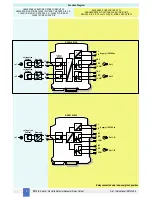
The Switch/Proximity Detector Repeater type D1130 is a DIN Rail unit with one or two independent channels. The unit can be configured for contact or proximity
detector, NO or NC and for NE or ND SPDT relay output contact. Each channel enables a Safe Area load to be controlled by a switch, or a proximity detector, located in Hazardous Area.
D1130D dual channel
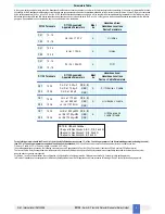
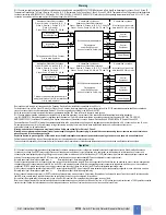
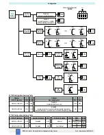
type has two independent input channels and actuates the corresponding output relay. Two actuation modes can be independently DIP switch configured on
each input channel: NO input/NE relay or NO input/ND relay. Contact or proximity sensor and its connection line short or open circuit fault detection is also DIP switch configurable:
fault detection can be enabled (in case of fault it de-energizes the corresponding output relay and turns the fault LED on) or disabled (in case of fault the corresponding output relay
repeats the input line open or closed status as configured).
D1130S single channel
type has one input channel and two output relays; the unit has two DIP switch configurable operating modes:
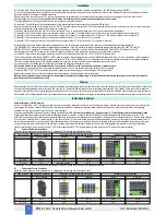
Mode A) input channel actuates in parallel the two output relays (DPDT contact). Relay actuation mode can be independently configured for each output in two modes: NO input/NE
relay or NO input/ND relay.
Mode B) input channel actuates output relay A configurable in two modes as in mode A above. Output relay B operates as a fault output (in case of input fault, relay B actuates and the
fault LED turns on while relay A repeats the input line as configured).
Actuation can be DIP switch configured in two modes: No input fault/energized relay (it de-energizes in case of fault) or No input fault/de-energized relay (it energizes in case of fault).
Function:
1 or 2 channels I.S. switch repeater for contact or EN60947-5-6 proximity. Provides 3 port isolation (input/output/supply).
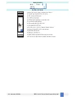
Signalling LEDs:
Power supply indication (green), output status (yellow), line fault (red).
Field Configurability:
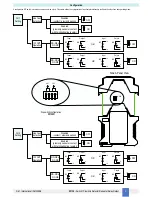
NO/NC input for contact/proximitor, NE/ND relay operation and fault detection enable/disable.
EMC:
Fully compliant with CE marking applicable requirements.
Supply:
115-230 Vac, 50-60 Hz nom (85 to 250 Vac, 48 to 400 Hz), ripple within voltage limits
≤
10 Vpp. Limit supply voltage to 250 Vrms for Instrinsic Safety applications.
Current consumption @ 115 Vac:
25 mA with short input and relays energized.
Current consumption @ 230 Vac:
15 mA with short input and relays energized.
Max. power consumption:
at 250 Vac supply voltage, short circuit input and relays energized, 2.0 W for 2 channels D1130D, 1.9 W for 1 channel D1130S.
Isolation (Test Voltage):
I.S. In/Out 2.5 KV; I.S. In/Supply 2.5 KV; Out/Supply 2.5 KV; Out/Out 2.5 KV.
Input switching current levels:
ON
≥
2.1 mA, OFF
≤
1.2 mA, switch current
≈
1.65 mA ± 0.2 mA hysteresis.
Fault current levels:
open fault
≤
0.2 mA, short fault
≥
6.8 mA
(when enabled both faults de-energize channel relay with dual channel unit D1130D or actuate fault relay with single channel unit D1130S).
Input equivalent source:
8 V 1 K
Ω
typical (8 V no load, 8 mA short circuit).
Output:
voltage free SPDT relay contact.
Contact material:
AgCdO.
Contact rating:
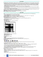
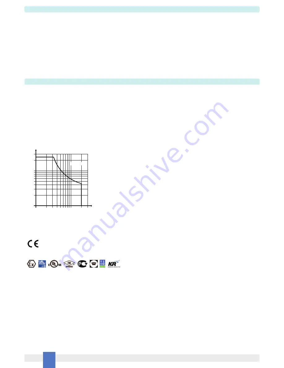
2 A 250 Vac 500 VA, 2 A 250 Vdc 80 W (resistive load).
DC Load breaking capacity:
Mechanical / Electrical life:
30 * 10
6
/ 1 * 10
5
operation, typical.
Operate / Release time:
7 / 3 ms typical.
Bounce time NO / NC contact:
3 / 5 ms.
Response time:
20 ms.
Frequency response:
10 Hz maximum.
Compatibility:
CE mark compliant, conforms to 94/9/EC Atex Directive and to 2004/108/CE EMC Directive.
Environmental conditions:
Operating:
temperature limits -20 to + 60 °C, relative humidity max 90 % non condensing, up to 35 °C.
Storage:
temperature limits – 45 to + 80 °C.
Safety Description:
II (1) G [Ex ia Ga] IIC, II (1) D [Ex ia Da] IIIC, I (M1) [Ex ia Ma] I, II 3G Ex nA IIC T4, [Ex ia Ga] IIC, [Ex ia Da] IIIC, [Ex ia Ma] I associated electrical apparatus.
Uo/Voc = 10.7 V, Io/Isc = 15 mA, Po/Po = 39 mW at terminals 13-14, 15-16.
Um = 250 Vrms, -20 °C
≤
Ta
≤
60 °C.
Approvals:
DMT 01 ATEX E 042 X conforms to EN60079-0, EN60079-11, EN60079-26, EN61241-0, EN61241-11,
IECEx BVS 07.0027X conforms to IEC60079-0, IEC60079-11, IEC60079-26, IEC61241-0, IEC61241-11, GM International CRR028 conforms to EN60079-0, EN60079-15,
UL & C-UL E222308 conforms to UL913 (Div.1),UL 60079-0 (General, All Zones), UL60079-11 (Intrinsic Safety “i” Zones 0 & 1) for UL and
CSA-C22.2 No.157-92 (Div.1), CSA-E60079-0 (General, All Zones), CSA-E60079-11 (Intrinsic Safety “i” Zones 0 & 1) for C-UL,
refer to control drawing ISM0143 for complete UL and C-UL safety and installation instructions,
FM & FM-C No. 3024643, 3029921C, conforms to Class 3600, 3610, 3611, 3810 and C22.2 No.142, C22.2 No.157, C22.2 No.213, E60079-0, E60079-11, E60079-15,
Russia according to GOST 12.2.007.0-75, R 51330.0-99, R 51330.10-99 [Exia] IIC X, Ukraine according to GOST 12.2.007.0,22782.0,22782.5 Exia IIC X,
DNV and KR Type Approval Certificate for marine applications.
Mounting:
T35 DIN Rail according to EN50022.
Weight:
about 145 g D1130D, 140 g D1130S.
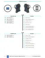
Connection:
by polarized plug-in disconnect screw terminal blocks to accomodate terminations up to 2.5 mm
2
.
Location:
Safe Area/Non Hazardous Locations or Zone 2, Group IIC T4, Class I, Division 2, Groups A, B, C, D Temperature Code T4 and Class I, Zone 2, Group IIC, IIB, IIA
T4 installation.
Protection class:
IP 20.
Dimensions:
Width 22.5 mm, Depth 99 mm, Height 114.5 mm.
Technical Data
Characteristics
0.2
0.1
V (V)
I (A)
10
20
30
40
50
100
200
300
0.3 0.5
1
2
5
Resistive
Load


