Calibrating the 3TB
5.1.3 Obtaining copies of the calibration pack
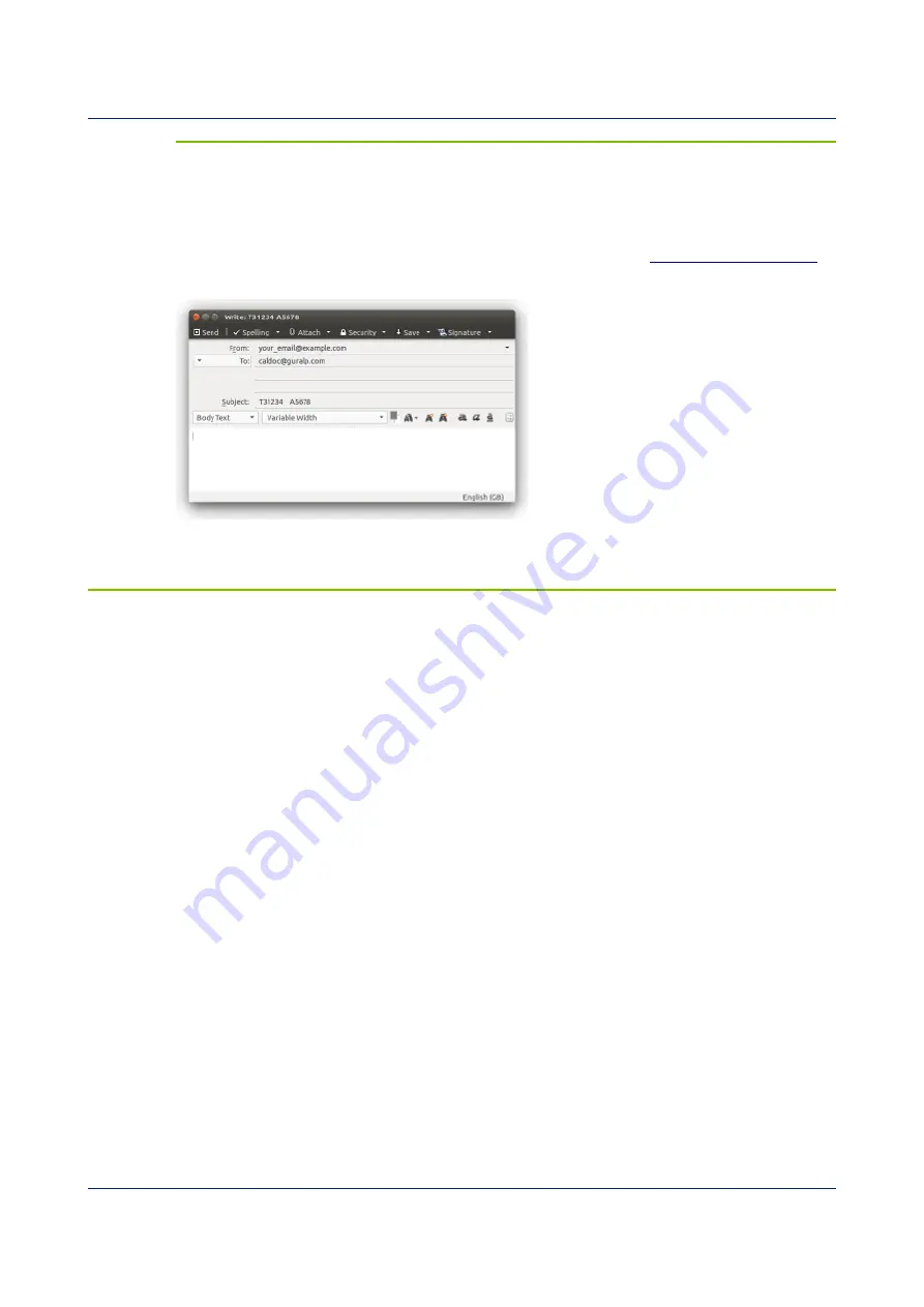
Our servers keep copies of all calibration data that we send out. In the event that the
calibration information becomes separated from the instrument, you can obtain all
the information using our free e-mail service. Simply e-mail
with the serial number of the instrument in the subject line,
e.g.
The server will reply with the calibration documentation in Word format. The body of
your e-mail will be ignored.
5.2 Calibration methods
Velocity sensors such as the 3TB are not sensitive to constant DC levels, either as a
result of their design or because of an interposed high-pass filter. Instead, three
common calibration techniques are used.
•
Injecting a step current allows the system response to be determined in the
time domain. The amplitude and phase response can then be calculated
using a Fourier transform. Because the input signal has predominantly low-
frequency components, this method generally gives poor results. However, it
is simple enough to be performed daily.
•
Injecting a sinusoidal current of known amplitude and frequency allows the
system response to be determined at a spot frequency. However, before the
calibration measurement can be made the system must be allowed to reach a
steady state; for low frequencies, this may take a long time. In addition,
several measurements must be made to determine the response over the full
frequency spectrum.
•
Injecting white noise into the calibration coil gives the response of the whole
system, which can be measured using a spectrum analyser.
You can perform calibration either using a Güralp DM24 digitizer, which can
generate step and sinusoidal calibration signals, or by feeding your own signals into
the instrument through a hand-held control unit.
53
Issue G - November 2019


