background image


40                            NS3000 UPS 60KVA~120KVA User Manual 

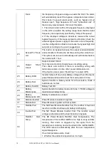
enable UPS to transfer to inverter. 

42 

Battery Volt Low 

Battery Voltage is Low. Before the end of discharging, battery 
voltage  is  low  warning  should  occur. After  this  pre-warning, 
battery should have the capacity for 3 minutes discharging with 
full load.   

43 

Battery Reverse 

Battery cables are connected not correctly. 

44 

Inverter


Protect 

The N# Power Module Inverter Protect. Check: 
Whether inverter voltage is abnormal 
Whether inverter voltage is much different from other modules, 
if  yes,  please  adjust  inverter  voltage  of  the  power  module 
separately. 

45 

Input 

Neutral 

Lost 

The mains neutral wire is lost or not detected. For 3 phases 
UPS,  it’s  recommended  that  user  use  a  3-poles  breaker  or 
switch between input power and UPS. 

46 

Bypass Fan Fail 

At least one of bypass module Fans Fails 

47 

Manual 
Shutdown 

The  N#  Power  Module  is  manually  shutdown.  The  power 
module  shuts  down  rectifier  and  inverter,  and  there’s  on 
inverter output. 

48 

Manual 

Boost 

Charge 

Manually force the Charger work in boost charge mode. 

49 

Manual 

Float 

Charge 

Manually force the charger work in float charge mode. 

50 

UPS Locked 

Forbidden to shutdown UPS power module manually. 

51 

Parallel 

Cable 

Error 

Parallel cables error. Check: 
If  one  or  more  parallel  cables  are  disconnected  or  not 
connected correctly 
If parallel cable round is disconnected 
If parallel cable is OK 

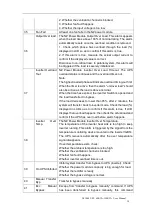
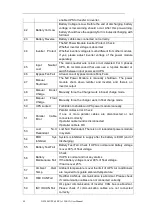
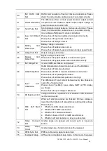
53 

Lost 

N+X 

Redundant 

Lost N+X Redundant. There is no X redundant powers module 
in system. 

54 

EOD 

Sys 

Inhibited 

System is inhibited to supply after the battery is EOD (end of 
discharging) 

55 

Battery Test Fail 

Battery Test Fail. Check if UPS is normal and battery voltage 
is over 90% of float voltage. 

56 

Battery 
Maintenance Fail 

Check 
If UPS is normal and not any alarms 
If the battery voltage is over 90% of float voltage 
If load is over 25% 

57 

Ambient 

Over 

Temp 

Ambient temperature is over the limit of UPS. Air conditioners 
are required to regulate ambient temperature. 

58 

REC CAN Fail 

Rectifier CAN bus communication is abnormal. Please check 
if communication cables are not connected correctly. 

59 

INV IO CAN Fail 

IO  signal  communication  of  inverter  CAN  bus  is  abnormal. 
Please  check  if  communication  cables  are  not  connected 
correctly. 

Содержание NS3000 Series

Страница 1: ...NS3000_60 120KVA User Manual ENG rev 02I Uninterruptible power supply NS3000 series 60 120kVA 3 3 UPS USER Manual...

Страница 2: ...Engineer Maintenance Engineer Note Our company is providing a full range of technical support and services Customer can contact our local office or customer service center for help The manual will up...

Страница 3: ...7 2 3 5 ECO Mode 8 2 3 6 Auto restart Mode 8 2 3 7 Frequency Converter Mode 8 2 4 UPS Structure 8 2 4 1 UPS Configuration 8 2 4 2 UPS Outlook 9 3 Installation Instruction 11 3 1 Location 11 3 1 1 Ins...

Страница 4: ...e 48 5 2 3 Switching the UPS into Normal Mode from Bypass Mode 49 5 2 4 Switching the UPS into Maintenance Bypass Mode from Normal Mode 49 5 2 5 Switching the UPS into Normal Mode from Maintenance Byp...

Страница 5: ...NS3000_60 120KVA User Manual ENG rev 02V Contents 7 5 Efficiency 62 7 6 Display and Interface 62 Appendix A 63...

Страница 6: ......
Страница 7: ...y and familiar with the operation debug and maintenance of the equipment Warning Label The warning label indicates the possibility of human injury or equipment damage and advises the proper step to av...

Страница 8: ...t 10 minutes for internal discharge Use a multi meter to measure the voltage on terminals and ensure the voltage is lower than 36V before operation Attention The earth leakage current of load will be...

Страница 9: ...with new product Otherwise battery capacity reduction electric leakage or fire may be caused Before operating the battery remove the finger ring watch necklace bracelet and any other metal jewelry We...

Страница 10: ...sposed of as urban waste The product s components must be disposed of separately as a Weee Any violations are punishable in accordance with the current regulations Improper disposal of the product or...

Страница 11: ...UPS structure is shown in Fig 2 1 Fig 2 1 UPS Configuration 2 2 Power Module The power module structure is shown as Fig 2 2 The power module contains a rectifier an inverter and a DC DC converter for...

Страница 12: ...ration diagram 2 3 2 Battery Mode Upon failure of the AC mains input power the inverter of power modules which obtain power from the battery supply the critical AC load There is no interruption in pow...

Страница 13: ...pically set to be less than 3 4 of an electrical cycle e g less than 15ms 50Hz or less than 12 5ms 60Hz The action of transfer re transfer can also be done by the command through monitor Rectifier AC...

Страница 14: ...rter shuts down when the battery reaches the End of Discharge Voltage EOD The UPS may be programmed to System Auto Start Mode after EOD The system starts after a delay time when the AC mains recovers...

Страница 15: ...NS3000 UPS 60KVA 120KVA User Manual 9 2 4 2 UPS Outlook The UPS outlook is shown as Fig 2 8 to Fig 2 11 Fig 2 8 60KVA System outlook Anchor Bolt Front Door Dust Filter Fig 2 9 90 120KVA System outlook...

Страница 16: ...Cable Connectors Dry contact Cold Start Main Input CB Ouput CB Maintenance Bypass CB Bypass CB LCD Control Panel Power Module Cable Entry Hole Fig 2 10 90 120KVA System outlook Front View Cabinet Aer...

Страница 17: ...ll generate a little amount of hydrogen and oxygen at the end of charging ensure the fresh air volume of the battery installation environment must meet EN50272 2001 requirements If external batteries...

Страница 18: ...12 NS3000 UPS 60KVA 120KVA User Manual Fig 3 1 Size of the 60KVA UPS Unit mm Fig 3 2 Size of the 90 120KVA for the cabinet Unit mm...

Страница 19: ...ght for the cabinet Configuration Weight UPS 60KVA 176Kg UPS 90KVA 231Kg UPS 120KVA 266kg 3 2 Unloading and Unpacking 3 2 1 Moving and Unpacking of the Cabinet The steps to move and unpack the cabinet...

Страница 20: ...top plate of the steel edged wooden case with slotted awl and pier followed by side boards see Fig 3 4 Fig 3 4 Disassemble the case 4 Remove the protective foam around the cabinet Fig 3 5 Remove the...

Страница 21: ...e materials of unpacking should be disposed to meet the demand for environmental protection 3 3 Positioning 3 3 1 Positioning Cabinet The UPS cabinet has two way of supporting itself One is to support...

Страница 22: ...equipment is needed when the mounting floor is not solid enough to support the cabinet which helps distribute the weight over a larger area For instance cover the floor with iron plate or increase the...

Страница 23: ...UPS power cables are recommended in Table 3 2 Table 3 2 Recommended cables for power cables Contents 60KVA 90KVA 120KVA Main Input Main Input Current A 110 165 220 Cable Section mm A 35 50 95 B 35 50...

Страница 24: ...ower Cables Terminal Specifications for power cables connector are listed as Table 3 3 Table 3 3 Requirements for power module terminal Port Type Connection Bolt Bolt Aperture Torque Moment Mains inpu...

Страница 25: ...the protective earth wire to protective earth terminal PE 4 Connect the AC input supply cables to the Input terminal and AC output supply cables to the Output terminal 5 Connect the Battery cables to...

Страница 26: ...ronmental temperature J3 2 TEMP_COM Common terminal for temperature detection J4 1 REMOTE_EPO_NC Trigger EPO when disconnect with J4 2 J4 2 24V_DRY 24V J4 3 24V_DRY 24V J4 4 REMOTE_EPO_NO Trigger EPO...

Страница 27: ...ing J10 3 UTILITY_FAIL_GND Common terminal for J10 1 and J10 2 Note The settable functions for each port can be set by the monitor software The default functions of each port are described as follows...

Страница 28: ...description is shown in Table 3 7 EPO_NC 24V 24V Fig 3 15 Diagram of input port for remote EPO Table 3 7 Description of input port for remote EPO Port Name Function J4 1 REMOTE_EPO_NC Trigger EPO when...

Страница 29: ...1 BCB_DRIV BCB contact drive provides 24V voltage 20mA drive signal J6 2 BCB_Status BCB contact status connect with the normally open signal of BCB J7 1 GND_DRY Power ground for 24V J7 2 BCB_Online BC...

Страница 30: ...The default function of J9 is the general alarm output dry contact interface When one or more warnings are triggered an auxiliary dry contact signal will be active via the isolation of a relay The int...

Страница 31: ...ram Table 3 12 Utility failure warning dry contact interface description Port Name Function J10 1 UTILITY_FAIL_NC Mains failure warning relay normally closed will be open during warning J10 2 UTILITY_...

Страница 32: ...icator 7 Inverter indicator 8 Load indicator 9 Battery indicator 10 Bypass transfer 11 Inverter transfer 12 Mute Figure 4 1 Control and display panel The LCD panel for cabinet is divided into three fu...

Страница 33: ...t least one module Steady red System output not supplied by inverter inverter fault for at least one module Flashing red System output supplied by inverter inverter fault for at least one module Off I...

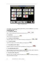
Страница 34: ...LCD touch Screen Users can easily browse the information operate the UPS and set the parameters through the LCD touch screen which is friendly for users After the monitoring system starts self test th...

Страница 35: ...ed parameters through main menu The structure of the main menu tree is shown in Figure 4 3 Home Cabinet Power unit Setting Log Operate Scope Bypass Main Output Load Battery Input Output Load Info S co...

Страница 36: ...t the various UPS power paths and show the current UPS operating status The green square indicating the block working normally the white indicating the absent of the block and red indicating the absen...

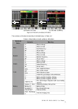
Страница 37: ...ase voltage A Phase current Hz Bypass frequency PF Power factor Output V Phase voltage A Phase current Hz Output frequency PF Power factor Load kVA Sout Apparent Power kW Pout Active Power kVar Qout R...

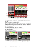
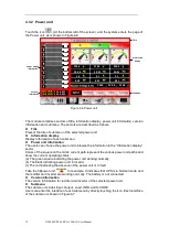
Страница 38: ...mation of each submenu Power unit information The users can choose the power unit to browse the information in the Information display sector Colors of the square on the mimic current path represent t...

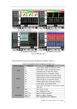
Страница 39: ...module A Input phase current of selected module Hz Input frequency of selected module PF Input power factor of selected module Output V Output phase voltage of selected module A Output phase current...

Страница 40: ...Y DD MM YY YY MM DD 2014 02 14 11 28 42 Setting interface Figure 4 8 Setting menu The submenus are listed on the right side of the Setting page Users can enter each of the setting interfaces by touchi...

Страница 41: ...umber of the battery 12V Battery Capacity Setting of the AH of the battery Float Charge Voltage Cell Setting the floating Voltage for battery cell 2V Boost Charge Voltage Cell Setting the boost Voltag...

Страница 42: ...letely equal to the real installed number Otherwise it will cause serious damage to the batteries or the equipment 4 3 4 Log Touch the icon At the bottom of the screen and the system enters the interf...

Страница 43: ...the amplitude or frequency of bypass voltage exceeds the limit The alarm will automatically reset if the bypass voltage becomes normal First check if relevant alarm exists such as bypass circuit break...

Страница 44: ...if there is something wrong with terminals sockets or some other power distribution unit If the fault is solved press Fault Clear to restart UPS 25 Battery EOD Inverter turned off due to low battery...

Страница 45: ...inverter Switch is opened and the load transferred to bypass If the load decreases to lower than 95 after 2 minutes the system will transfer back to inverter mode Check the load displayed in LCD so a...

Страница 46: ...he Charger work in boost charge mode 49 Manual Float Charge Manually force the charger work in float charge mode 50 UPS Locked Forbidden to shutdown UPS power module manually 51 Parallel Cable Error P...

Страница 47: ...rter IGBTs are broken and opened 68 Outlet Temp Error Outlet temperature of power module is over the limitation Please check if fans are abnormal Please check if PFC or inverter inductors are abnormal...

Страница 48: ...t air is over temperature Make sure that the operation temperature of UPS is between 0 40 C 81 Capacitor Time Reset Reset timing of DC bus capacitors 82 Fan Time Reset Reset timing of fans 83 Battery...

Страница 49: ...ng Error Manufacturer used only 107 Bypass Over Temp Bypass module is over temperature Please check If bypass load is overload If ambient temperature is over 40 C If bypass SCRs are assembled correctl...

Страница 50: ...Bypass Transfer to bypass mode or cancel this command by touching the icon or Transfer to Inverter Transfer the bypass mode to Inverter Mode by touching the icon Enable Module OFF Button Enable the sw...

Страница 51: ...for the battery Battery Boost By touching the icon the system starts boost charging Battery Float By touching the icon the system starts float charging Stop Test By touching the icon the system stops...

Страница 52: ...000 UPS 60KVA 120KVA User Manual Touch the icon to display the 3 phase output current Touch the icon to display the 3 phase bypass voltage Touch the icon to zoom in the wave Touch the icon to zoom out...

Страница 53: ...ing Inverter off Battery red Load off Bypass off Status red 5 After 30S the rectifier indicator goes steady green presenting the finishing of rectification and then the inverter is starting up The LED...

Страница 54: ...ion of the battery cold start button 3 After that the system is starting up following steps 3 in section 5 1 1 and the system transfers to battery mode in 30S 4 Close the external output power supply...

Страница 55: ...cy of the bypass is over track and when the system needs to transfer to Normal mode by manual 5 2 4 Switching the UPS into Maintenance Bypass Mode from Normal Mode These following procedures can trans...

Страница 56: ...the rectifier starts the rectifier indicator LED goes green and then inverter starts 6 After 60S the system transfers to Normal mode 5 3 Battery Maintenance If the battery is not in use for a long tim...

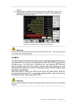
Страница 57: ...display panel with cover to avoid disoperation see Fig 5 5 is designed to switch off the UPS in emergency conditions e g fire flood etc To achieve this just press the EPO button and the system will t...

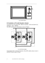
Страница 58: ...n System The system can have three UPS cabinets in parallel which can extend to a capacity of total 360KVA Two UPS cabinets are connected as is shown in Fig 5 6 Fig 5 6 Parallel diagram The parallel b...

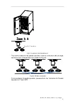
Страница 59: ...Parallel board The control cables for the parallel operation must be connected with all single devices to form a closed loop as is shown in Fig 5 8 Fig 5 8 Parallel connection For more details of para...

Страница 60: ...needed to be repaired 1 Ensure the remaining power module will not be overloaded 2 Power off the power unit a Enable LCD panel Menu Operate Enable Module OFF icon b Press the OFF button on the power...

Страница 61: ...tting of Battery Number 1 Setting battery number for Lead Acid battery The nominal voltage of one block battery is 12V and for each block of battery it consists of 6 cells each cell of 2V For the sett...

Страница 62: ...e Setting In boost charging the system charges the batteries with constant current After the period the system will enter the float charging For the Lead Acid battery the default float charge voltage...

Страница 63: ...s for setting the Auto boost period time The system boost charges the battery when the reaching the Auto boost period It is suggested to boost charge the battery every three month set the period to 43...

Страница 64: ...of UPS EN50091 3 IEC62040 3 AS 62040 3 VFI SS 111 Note The above mentioned product standards incorporate relevant compliance clauses with generic IEC and EN standards for safety IEC EN AS60950 electro...

Страница 65: ...4 1 Electrical Characteristics Input Rectifier Table 7 5 Rectifier AC input Mains Item Unit Parameter Grid System 3 Phases Neutral Ground Rated AC Input Voltage Vac 380 400 415 three phase and sharing...

Страница 66: ...voltage 1 Ripple current 5 Equalized charge voltage VRLA 2 4V cell selectable from 2 30V cell 2 45V cell Constant current and constant voltage charge mode Final discharging voltage V cell VRLA 1 65V...

Страница 67: ...ncy Regulation Hz 50 60Hz 0 1 Voltage precision 1 5 0 100 linear load Overload 110 60min 125 10min 150 1min 150 200ms Synchronized Range Hz Settable 0 5Hz 5Hz default 3Hz Synchronized Slew Rate Hz Set...

Страница 68: ...between bypass and inverter ms Synchronized transfer 0ms Bypass voltage range Settable default 20 15 Up limited 10 15 20 25 Down limited 10 15 20 30 40 Bypass frequency range Hz Settable 1Hz 3Hz 5Hz...

Страница 69: ...C server verify the setting on UPS Mimic Panel select Comm Set set Protocol SNT UPSilon use description UPSilon is a UPS monitoring and shutdown software which provides user friendly interface to moni...

Отзывы: