


3. Installation
PNEG-1993
CE Compliant E-Series Chain Conveyors - All Models
23
Assembling an Un-Assembled Intermediate Section
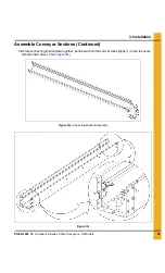
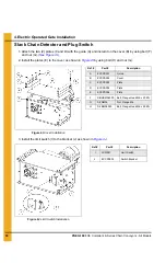
Figure 3C Intermediate Trough Assembly
1. Assemble A.
2. Install C.
3. Check dimensions.
4. Leave B off.
Figure 3D Check Dimensions
Ref #
Description
Hardware
A
Bottom Plate
M08 - Flat Head Socket Cap Screw
M08 - Flange Nut
B
Cover
M06 - Flange Bolts
M06 - Flange Nuts
C
Rail Return
M06 - Button Head Screw
Ref #
Description
D
Nominal width of conveyor
E
It must be same for left and right rail


