5
384V500AH
640V2520AH
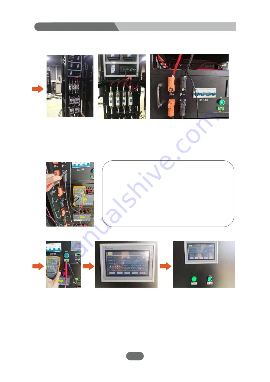
2. Please follow the steps below to implement the power-on process:
Check the power lines between the battery packs and
whether the communication lines are properly
connected and fastened.
Set the multimeter to the DC voltage position, the red
test pen touches B+ of the battery cluster high voltage
control box, and the black test pen touches B- of the
battery cluster high voltage control box. Check whether
the voltage of each battery cluster tends to be the same
(the voltage difference is within 0.5V) and make sure it
is the positive voltage.
Close the battery breaker
BAT/SW of the fifth cluster,
power on the system with
weak current, and the display
screen on the system cabinet
starts to work, press the
ON/OFF button switch on the
system cabinet
Turn on the BAT/SW and
RUN buttons of the battery
circuit breakers of each
cluster in turn, then BAU will
check whether each BCU is
online normally, and the
system will self-check
The power lines P+ and P- of each cluster are connected to the system
cabinet according to the CAD drawings.
Set the multimeter to the
electric blocking position,
and the red and black test
leads respectively touch the
two poles of the debugging
CAN port (regardless of
positive and negative), and
confirm whether the
resistance value is about 60
Ω
Содержание 640V2520AH
Страница 5: ...3 384V500AH 640V2520AH Battery module layout and signal cable connection diagram Overall...
Страница 35: ......
Страница 36: ...High Voltage Lithium Iron Phosphate Battery...


