background image

PHP A-1 Instruction Manual / 

Cleaning and maintenance

 8 

   Cleaning and maintenance

 8.1   Cleaning

During operation, mud particles will be caught inside the 
filter of the mud flap which is mounted at the connection 
of the expansion overflow pipe. Due to these impurities the 
flow rate through the mud flap decreases. This decrease 
could lead to malfunctions of the device.

So the mud particles must be removed in periodic intervals 
by dismantling and cleaning of the filter of the mud flap. This 
check and cleaning of the mud flap must be done at least 
two times a year. If any problems appear at the pressure 
maintenance device, you should clean the mud flap at first.

Any problems or malfunctions caused by missing this 
cleaning are excluded from any warranty.

 8.2   Maintenance

Maintenance is required at least once a year or if the warning 
W3 is displayed. The operator has do take care that this 
maintenance will be done effectively.

  RECOMMENDATION. 

If problems with impurities appear frequently, further 
tasks must be considered (e.g.) changing and flushing 
of the plant media, installation of additional filters or  
mud separators,...)

These measures affect positively to the entire plant, not 
only to the pressure maintenance device.

  NOTE 

If this maintenance can‘t be done resp. isn’t intended to  
be done by the operator himself, an adequate expert or  
the Grundfos customer service must be assigned to do it.

  INFORMATION 

We recommend that the maintenance is executed by the 
Grundfos customer service. In this case a conclusion of a 
maintenance contract is highly recommended.

Any problems caused by missing the required maintenance 
or maintenance intervals are excluded from any warranty.

Works that must be done in the course of a maintenance:

•  Check and record, if the periodic cleaning acc. to 8.1 hast

been done, record the last cleaning. Clean the device
acc. to 8.1 in every case.

•  Ask the operator and record, of there occurred

abnormalities or problems since the last maintenance.
If possible, resolve these problems.

•  Look for the correct closure of the check valve(s).

•  Look for the correct function and closure of the

overflow valve.

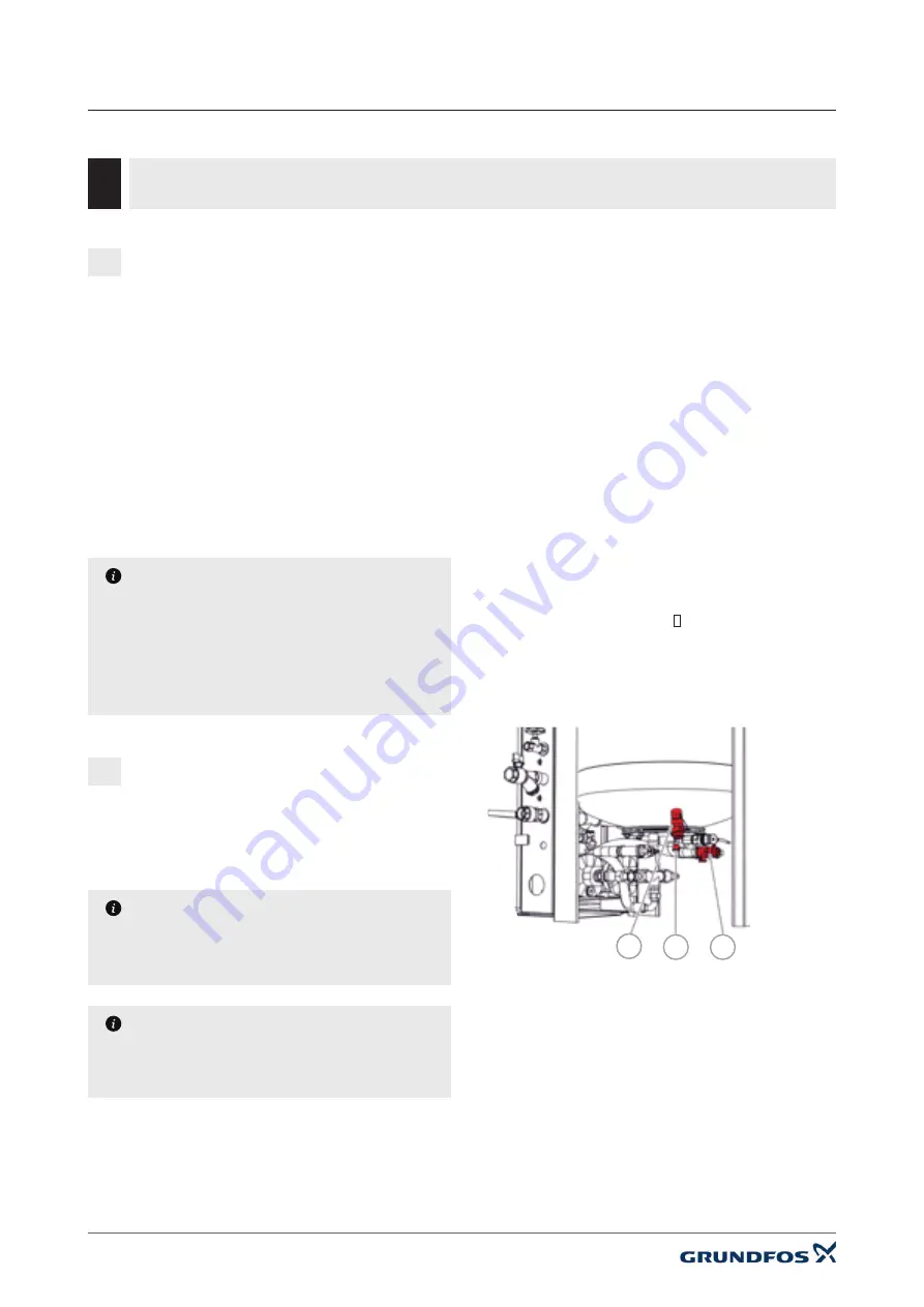
•  Elutriate the vessel via the tap at the lower vessel flange

(1) resp. in the overflow pipe at the vessel.

•  Open the drain tap (2) and discharge eventually existing

medium. If medium discharges permanently, the
membrane could be damaged   Check the membrane.

•  Flush the connection of the vessel pressure transmitter

(3). Open the black plastic plug and flush out of the vessel
until any impurities are removed. Then close the plug.

3

2

1

43

Содержание PHP A-1 4.0

Страница 1: ...PHP A 1 4 0 5 6 6 6 8 1 Instruction manual UK version original instructions...

Страница 2: ...ke up water PUMPS 7 Warnings and fault messages 8 Cleaning and maintenance 8 1 Cleaning 8 2 Maintenance 9 Technical data 9 1 PHP 9 2 Additional expansion vessels for combination with PHP 10 Spare part...

Страница 3: ...d All operations are controlled by the microprocessor electronics The operator panel is situated ergonomically and contains an illuminated 4 line text display The measure and control unit is executed...

Страница 4: ...no external pressures can occur External pressures could affect the trouble free operation of the pressure maintenance device The dimension of the expansion pipe is determined acc to the standard NOR...

Страница 5: ...PHP A 1 Instruction Manual Mounting 05 Figure 1 Changing the positions of the hydraulic connections...

Страница 6: ...able bushings in gland plate are also situated at the right side of the device If necessary they can also be built to the left side Figure 2a The opening on the other side must be closed by using the...

Страница 7: ...be insulated too Figure 7 Usage of a cooling vessel NOTE The automatic degassing feature will be disabled if a bypass set is used The degassing function must be disabled using the device set up featur...

Страница 8: ...the system return must be executed on site the sensor must be mounted immediately in front of the connection to the pressure maintenance device Figure 8a If a cooling vessel is used the sensor must be...

Страница 9: ...Makeup water 2 Expansion overflow pipe from system return min DN25 3 Expansion pressure pipe to system return min DN25 4 Discharge hopper for vessel safety valve 5 Suction pipe from expansion vessel 6...

Страница 10: ...additional vessels expansion modules makeup module EMCF 1 V sensor T2 1 Makeup water 2 Expansion overflow pipe from system return min DN25 3 Expansion pressure pipe to system return min DN25 4 Dischar...

Страница 11: ...tional vessels expansion modules cooling vessel makeup module EMCF 1 V sensor T2 1 Makeup water 2 Expansion overflow pipe from system return min DN25 3 Expansion pressure pipe to system return min DN2...

Страница 12: ...PHP A 1 Instruction Manual Wiring diagrams 4 Wiring diagrams 12 4 1...

Страница 13: ...PHP A 1 Instruction Manual Wiring diagrams 13...

Страница 14: ...PHP A 1 Instruction Manual Wiring diagrams 14...

Страница 15: ...78 Date Date Replaced by 11 Revision 10 17 16 Appr Replacement of 18 19 13 6 14 07 05 2019 12 Name 15 PHP Control Panel Ferryboat Lane Castletown Sunderland Tyne and Wear SR5 3JL DRAWING No Sheet of 6...

Страница 16: ...tegrated OPTION M1 Motor of pump 1 M2 Motor of pump 2 OPTION Y1 Makeup module magnetic valve OPTION B1 Makeup module water meter pulse output OPTION B2 Lower vessel pressure transmitter PL2u B3 Upper...

Страница 17: ...rs are disabled Only the sensor system remains active Caution no pressure maintenance in this mode Execute function The function displayed above the key is executed directly Change values Keys to rais...

Страница 18: ...display via a flashing cursor 18 UE User element Description Notice Select apply Selecting a menu item resp applying changed settings Back Back to previous menu resp previous display without confirmin...

Страница 19: ...1 max and current state min level L min and current state max level L max and current state min temperature T1 min and current state max temperature T1 max and current state min temperature T2 min and...

Страница 20: ...T2 7 number of times the temperature limit was overrun from resettable general version time and date device type enable contact SMS module 12 PHP A 1 Instruction Manual Operation and display 20 1 Only...

Страница 21: ...for degassing degassing fast fast degassing active break fast shortened break because fast degassing is active degassing normal degassing cycle is active break normal normal break because fast degassi...

Страница 22: ...erating states over defined periods resettable DISPLAY LEVEL 2 GENERAL current software version current time and date set type model of the device current status of the enable contact On or Off DISPLA...

Страница 23: ...an only with special display CT b Romanian b Polish b Czech b Latvian b Croatian c Estonian c USER LEVEL 2 ACTIONS One time filling stop filling Vessel will be filled to a defined level one time only...

Страница 24: ...min max temperature T1max min temperature T2min 7 max temperature T2max 7 general main display language time date display contrast bus module web module 16 enable receiving enable device only if recei...

Страница 25: ...always run at the same time Selection of the used level measurement at devices with enabled second level measurement L2 automatic change Automatic change to the second level measurement L2 in case of...

Страница 26: ...of fast degassing default setting 48 h Timer program Cycle normal Cycle fast Durat fast degassing USER LEVEL 3 SETTINGS MONITORING In this settings you can define maximum and minimum values for the r...

Страница 27: ...croll to setting block 2 select block 2 set the times On 16 00 Off 20 00 1 next scroll to setting block 3 select block 3 set the times On 24 00 Off 24 00 1 2 next back Step 1 scroll to setting Saturda...

Страница 28: ...deactivate the device by pressing the key 0 and following confirmation by pressing the key F1 red control lamp beside the key 0 must glow Version B Version A 1 2 3 Commissioning procedure STEP 1 Deter...

Страница 29: ...tying right beside the overflow valve and ventilate the piping completely by starting and stopping the pump s in manual mode several times After this shut the emptying PHP A 1 Instruction Manual Commi...

Страница 30: ...pipe expansion pressure pipe makeup water Due to the size of the system the setting of the working pressure can take up a lot of time because the pressure has to extend into the entire connected syst...

Страница 31: ...there are known and regular leakages e g a known makeup amount within a known period we recommend to use the operating mode time controlled For a description of the different operating modes see chap...

Страница 32: ...ture service 2 Connect the BSP Male OVERFLOW connection to drain 3 Allow the BREAKTANK to fill from the mains water connection and set the BALL FLOAT such that the BREAKTANK water level stops before i...

Страница 33: ...over run Built in monitoring has been activated The set maximum level has been exceeded Message is only an advice It doesn t affect the function of the device Check set limit value eventually no cont...

Страница 34: ...is only an advice The Sensor T2 is decided to disable degassing in such situations with too high temperatures sensor T2 W14 Wl4 monitoring T2max over run Built in monitoring has been activated the se...

Страница 35: ...dercuts of the minimum temperature at sensor T1 mean too low temperatures at the connection point On site steps e g EV ET vessel etc are necessary to avoid damage of the device e g armatures bubble et...

Страница 36: ...1 Z2 has been activated after cooling down pump can restart if necessary break incorrect contact defect output A_PHASE_0 no contained in every configuration E3 E3 PumP Ml stoP fai1ed Device control di...

Страница 37: ...circuit The resistance of the sensor is too low and falls below the valid range sensor connection shows a short circuit or is damaged sensor element is defective no contained in every configuration E9...

Страница 38: ...nal of pressure transmitter PL1u vessel pressure bottom is above the normal valid range connection of pressure transmitter PL1u is incorrect or damaged pressure transmitter is defective measure input...

Страница 39: ...expansion module is defective expansion module analogue signalling E19 E19 read error I2C modu1e binar si In The internal communication between the basic circuit board and the expansion module binary...

Страница 40: ...led Device control disabled the output A_PHASE_1 for pump M2 but after this at least one checkback signal of the pump motor DI_1 was received incorrect contact defect output A_PHASE_1 defect input DI_...

Страница 41: ...led again makeup module EMCF 1 V and softening MWE E29 E29 transmitter PL2o meas si Ina1 too hi Ih Measurement signal of pressure transmitter PL2o vessel pressure top is above the normal valid range c...

Страница 42: ...emineralisation cartridge is depleted a correct demineralisation is not ensured anymore Thus the EMCF 1 V makeup module is disabled too change cartridge and confirm it in the control electronics actio...

Страница 43: ...plant not only to the pressure maintenance device NOTE If this maintenance can t be done resp isn t intended to be done by the operator himself an adequate expert or the Grundfos customer service must...

Страница 44: ...8 2 4 6 6 6 0 7 8 6 0 10 4 6 0 10 4 2 4 6 2 2 4 6 2 2 4 6 2 2 4 6 2 2 4 6 6 6 0 10 1 2 4 6 6 6 0 10 1 2 4 6 6 2 4 6 6 8 0 16 0 8 0 16 0 2 4 6 6 6 0 11 0 2 4 6 6 6 0 11 0 bar 10 16 25 16 C 70 V Hz vol...

Страница 45: ...45 PHP A 1 Instruction Manual Technical data Modular PHP A 1 9 2 Additional expansion vessels for combination with PHP Design of expansion vessels 200 500 800 1 500 2 000 5 000 10 000...

Страница 46: ...Vessels nominal content litre 1 000 1 500 2 000 2 500 3 000 4 000 5 000 10 000 nominal pressure vessel PN bar 0 5 max temperature at plant connection C 70 insertion tip dimension mm 2300 2500 2600 34...

Страница 47: ...board PHP 200331 99478310 Spare PHP Analogue Board Board expansion module analogue signalling 90624 99478311 Spare PHP Binary board Board expansion module binary signalling 90625 99478312 Spare PHP L...

Страница 48: ...eakage A safety valve 0 5 bar is installed at the upper vessel flange This valve could open and discharge hot plant media due to the following reasons The device resp the expansion vessel was dimensio...

Страница 49: ...sion pipe you need to know the nominal power to be dissipated the max operating temperature and the flow speed acc to NORM H 5151 1 2010 12 15 DN Nominal power in kW 20 up to 120 20 from 120 to 500 Th...

Страница 50: ...ensure a correct function of the pressure maintenance unit you have to consider the following instructions for the connection between PHP and expansion vessels 800M and above 1 2 2 1 NOTE Overflow pip...

Страница 51: ...PHP A 1 Instruction Manual Appendix 51...

Страница 52: ...PHP A 1 Instruction Manual EC declaration of Conformity 52 13 EC declaration of Conformity...

Страница 53: ...GRUNDFOS PUMPS LTD Grovebury Road Leighton Buzzard Bedfordshire LU7 4TL T 01525 850 000 E grundfos uk sales grundfos com Article number 61 738_00 08 2019 Grundfos I O Manual PHP A 1 4 0 5 6 6 6 8 1...

Отзывы: