3
PUMP CONSTRUCTION
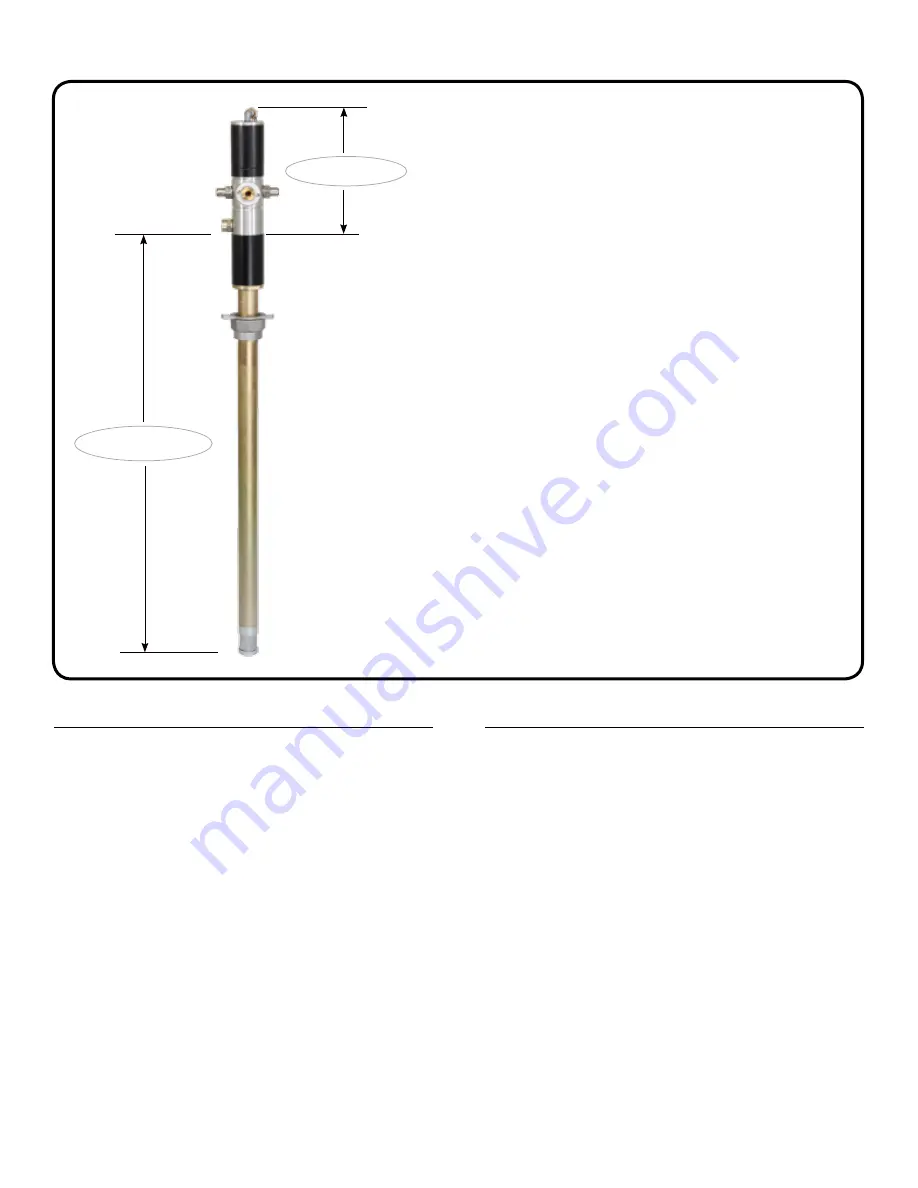
DRIVE SECTION
PUMPING SECTION
The pump is made up of two sections as below
:-
•
DRIVE SECTION
:- It consists of an Air Motor
Assembly driven by compressed air. The piston
diameter of the air motor is 2.5” / 63 mm. The motor
consists of an air cylinder with piston and one
reciprocal valve with a nylon slider. The valve directs
the compressed air alternately to the top or bottom of
the piston, thus producing a reciprocating motion of
the piston rod.
•
PUMPING SECTION
:- It consists of a pump in
which a piston lifts media through Non Return Valves
by reciprocating inside the suction tube. Media is
discharged with pressure (from the outlet located at
bottom of Air Motor) into the delivery hose / pipe.
NOTE
•
AIR MOTOR
of this pump starts automatically
when the dispensing gun / tap is opened. When the
dispensing gun / tap is closed, air motor builds up
a back-pressure and stops operating the pumping
section.
•
PRESSURE RATIO
of the pump states the ratio of the
output fluid pressure to the incoming air pressure.
Since the pressure ratio is 1:1, we achieve an output
media pressure up to 150 PSI (10 BAR) when the
incoming air pressure is 150 PSI (10 BAR).
•
AIR SUPPLY
: An FRL (Filter-Regulator-Lubricator) unit must
be used in the Air supply, before it is connected to the
pump.
Set the regulator to 6 BAR (90 PSI) or any required inlet
pressure, but never more than 150 PSI (10 BAR) or less
than 30 PSI (2 BAR).
When not in use & at the end of each day , air supply to the
pump must be switched off.
•
DISCHARGE HOSE
: It is recommended to use a hose with
½” I.D., with a Working Pressure of not less than 400 PSI
(28 BAR). Burst Pressure must be atleast 1000 PSI (70
BAR) or more. Using a smaller I.D. hose will cause higher
pressure loss.
•
DISPENSING GUN
: Based on the application, you may use
a gun that is compatible with media being dispensed.
•
THREAD SEALANT
: Apply thread sealant on all threaded
connections to ensure leak-proof operation.
GETTING STARTED
Before installing the pump, make sure the following are available:
1. Slide out the Bung from Suction Tube & screw it into the 2”
opening on the drum.
2. Loosen the ring nut on Bung & carefully insert the pump
Suction Tube through it. Once the Suction Tube touches the
bottom of drum, tighten the ring nut.
3. Connect the appropriate hose and dispensing gun to the
pump outlet. Use a thread sealant to avoid any leakage.
4. With the air supply turned off, connect the air line into the air
inlet on the pump. Remove the vent plug on drum to create
the required venting for pump operation.
5. Partially open the on/off air valve (It helps in creating initial
vacuum when filling a totally dry pump). Pump will start
operating automatically until it gets primed. Pump is said
to be
Primed
when media is available at the pump outlet,
making the pump ready to use. Once primed, the air motor
will stop. Open the on/off air valve fully.
6. Operate the dispensing gun / Oil Bar Tap, which will actuate
the air motor & pump will start dispensing.
PUMP INSTALLATION & OPERATION
Fig. 2


