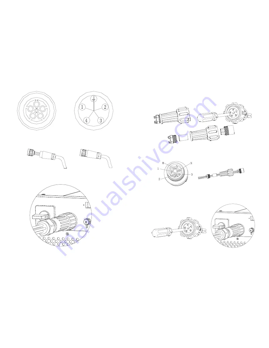
Fig 5.11
Fig 5.12
AC connector 2:
Assembly procedure:
1) Unscrew the AC connector by hand and slotted screwdriver into four components:
2) Tighten the left part and right part clockwise.
3) Connect it to the AC side of the inverter.
Fig 5.10
Fig 5.14
2) Connect 5 cables into their respective channels on the AC terminal, while 'N’
represents Neutral, '1, 2, 3' represent 3 line channels and 'E' is ground, tighten all
screws (1.0Nm (9 lbf.in.) max).
Fig 5.15
3) Insert the contact into the body with slotted screwdriver (1.13Nm (10 lbf.in.) to
1.36Nm (12 lbf.in.) ),screw up other components of the connector.
Fig 5.16
Fig 5.17
23
24


