background image

Model T32006 (Mfd. Since 01/20)

-12

-

Inventory

Your  tool  was  carefully  packaged  for 
safe  transportation.  Remove  the  packag-
ing  materials  from  around  your  tool  and 
inspect it. If you discover the tool is dam-
aged,  please immediately call Customer 
Service at (570) 546-9663 for advice. 

Save the containers and all packing mate-
rials  for  possible  inspection  by  the  car-
rier or its agent. Otherwise, filing a freight 
claim can be difficult.

When  you  are  completely  satisfied  with 
the  condition  of  your  shipment,  inventory 
the contents.

If  any  non-proprietary  parts  are  missing 
(e.g.,  a  nut  or  a  washer),  we  will  gladly 
replace  them;  or  for  the  sake  of  expedi-
ency,  replacements  can  be  obtained  at 
your local hardware store.

Unpacking

This 

tool

 presents serious injury 

hazards to untrained users. Read 
through this entire manual to 
become familiar with the controls 
and operations before starting the 
tool!

Needed for Setup

The  following  items  are  needed,  but  not 
included, for setup/assembly of this tool.

Safety Glasses ................................... 1 Pr.

Description 


            Qty.

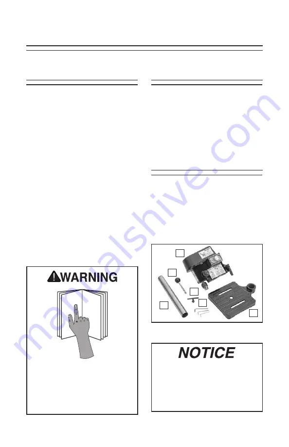
Inventory (Figure 4)
A.
  Headstock Assembly .........................1
B.  Column ...............................................1
C.  Downfeed Handle ..............................1
D.  Chuck Key ..........................................1
E.  Hex Wrenches 2, 2.5, 4mm ........ 1 Ea. 
F.  Table ..................................................1

If you cannot find an item on this 
list, carefully check around/inside 
the tool and packaging materials. 
Often, these items get lost in pack-
aging materials while unpacking or 
they are pre-installed at the factory.

SECTION 4: SETUP

B

Figure 4. Inventory.

A

F

E

D

C

B

Содержание T32006

Страница 1: ...ARNING NO PORTION OF THIS MANUAL MAY BE REPRODUCED IN ANY SHAPE OR FORM WITHOUT THE WRITTEN APPROVAL OF GRIZZLY INDUSTRIAL INC CS20890 PRINTED IN CHINA MODEL T32006 MINI BENCHTOP DRILL PRESS OWNER S MANUAL For models manufactured since 01 20 V1 03 20 ...

Страница 2: ...ng grinding tool integrity and the usage of personal protective equipment The manufacturer will not be held liable for injury or property damage from negligence improper training machine modifications or misuse Some dust created by power sanding sawing grinding drilling and other construction activities contains chemicals known to the State of California to cause cancer birth defects or other repr...

Страница 3: ...uctions for Power Tools OWNER S MANUAL Read and under stand this owner s manual BEFORE using machine TRAINED OPERATORS ONLY Untrained operators have a higher risk of being hurt or killed Only allow trained supervised people to use this power tool When tool is not being used disconnect power and store in out of reach location to prevent unauthorized use especially around children Make workshop kid ...

Страница 4: ...ger while carrying FORCING TOOLS Use right tool for job and do not force it It will do job safer and better at rate for which it was designed SECURING WORKPIECE When required use clamps or vises to secure workpiece This protects hands and frees both of them to operate tool GUARDS COVERS Guards and cov ers reduce accidental contact with mov ing parts or flying debris Ensure they are properly instal...

Страница 5: ...ed speeds and feeds for each size type of bit cutting tool and workpiece material SECURING BIT CUTTING TOOL Firmly secure bit cutting tool in chuck so it cannot fly out of spindle during opera tion or startup DRILLING PREPARATION To avoid loss of drilling control or bit breakage only drill into flat surface that is approximately per pendicular to bit Clear table of all objects before starting spin...

Страница 6: ... and photographs of the drill press we used when writing this manual However sometimes we still make an occasional mistake Also owing to our policy of continuous improvement your drill press may not exactly match the manual If you find this to be the case and the difference between the manual and drill press leaves you in doubt check our website for the latest manual update or call technical suppo...

Страница 7: ... Power Cord Gauge 18 AWG Plug Included Yes Included Plug Type 5 15 Switch Type Variable Speed Dial Motors Main Horsepower 1 8 HP Phase Single Phase Amps 0 95A Speed 0 5000 RPM Type Universal Power Transfer Belt Bearings Shielded Permanently Lubricated Main Specifications Operation Information Swing 8 3 4 in Spindle Taper B10 Spindle Travel 7 8 in Max Distance From Spindle to Column 4 3 8 in Max Di...

Страница 8: ...Variable Speed ON OFF Switch Downfeed Handle Belt Cover Table Spindle Chuck Headstock Lock Handle Column Depth Stop For Your Own Safety Read Instruction Manual Before Operating Drill Press a Wear eye protection b Do not wear gloves necktie or loose clothing c Clamp workpiece or brace against column to prevent rotation d Use recommended speed for drill accessory and workpiece material ...

Страница 9: ...Figure 2 Headstock controls C To reduce your risk of serious injury read this entire manual BEFORE using machine C Downfeed Handle Moves spindle down when pulled down Spindle auto matically returns to top position when released D Variable Speed ON OFF Switch Turn clockwise to turn motor ON and select desired speed Turn counterclockwise to lower speed and turn motor OFF E Headstock Lock Handle Lock...

Страница 10: ...uit that meets the requirements in the following section Full Load Current Rating Note The circuit requirements listed in this manual apply to a dedicated circuit where only one tool or machine will be run ning at a time If this tool will be connected to a shared circuit where multiple machines will be running at the same time consult a qualified electrician to ensure that the circuit is properly ...

Страница 11: ...grounding requirements or if you are in doubt about whether the tool is properly grounded If you ever notice that a cord or plug is damaged or worn dis connect it from power and immediately replace it with a new one Grounding Plug Requirements Figure 3 Typical 5 15 plug and receptacle Extension Cords Minimum Gauge Size 16 AWG Maximum Length 50 ft We do not recommend using an exten sion cord with t...

Страница 12: ...lace them or for the sake of expedi ency replacements can be obtained at your local hardware store Unpacking This tool presents serious injury hazards to untrained users Read through this entire manual to become familiar with the controls and operations before starting the tool Needed for Setup The following items are needed but not included for setup assembly of this tool Safety Glasses 1 Pr Desc...

Страница 13: ...le gloves Plastic paint scraper optional The unpainted surfaces of your machine are coated with a heavy duty rust preven tative that prevents corrosion during ship ment and storage This rust preventative works extremely well but it will take a little time to clean Be patient and do a thorough job cleaning your tool The time you spend doing this now will give you a better appreciation for the prope...

Страница 14: ... column place a block of wood over column use a small hammer to tap column into table then re install headstock 2 Tighten pre installed set screw to secure column in table see Figure 5 Figure 5 Location of set screw that secures column in table Column Table This tool must be fully assembled before it can be operated Before beginning the assembly process refer to Needed for Setup and gather all lis...

Страница 15: ...t run immediately stop the tool discon nect it from power and fix the problem BEFORE operating the tool again The Troubleshooting table in the SERVICE section of this manual can help The Test Run consists of verifying the following 1 The motor powers up and runs correctly To test run tool 1 Clear away all setup adjustment tools 2 Turn variable speed dial all the way counterclockwise see Figure 7 3...

Страница 16: ...clamp 4 Installs correct drill bit or cutting tool for operation 5 Adjusts headstock to correct height then locks it in place 6 Connects tool to power and turns tool ON 7 Selects appropriate spindle speed 8 Performs drilling operation 9 When finished turns tool OFF and dis connects it from power Due to the generic nature of this overview it is not intended to be an instructional guide To learn mor...

Страница 17: ...use for drilling Figure 8 Drill bit installed in chuck Chuck Drill Bit Adjusting Headstock Position The headstock moves vertically and pivots around the column 2 While holding headstock loosen head stock lock handle shown in Figure 9 Figure 9 Headstock lock handle location Headstock Lock Handle 3 Adjust headstock to desired position then tighten lock handle to secure Adjusting Depth Stop The depth...

Страница 18: ...lt in operator s hand being pulled into bit or workpiece being thrown with great force Always clamp workpiece to table to prevent and reduce risk of injury Twist Brad PointDrill Bits Soft Wood Hard Woods Plastic Brass Aluminum Mild Steel 1 16 3 16 3000 2500 2500 2500 3000 2500 13 64 3 8 2000 1500 2000 1250 2500 1250 25 64 5 8 1500 750 1500 750 1500 600 11 16 1 750 500 1000 400 1000 350 Spade Forst...

Страница 19: ...eed ranges 1 DISCONNECT TOOL FROM POWER 2 Squeeze sides of headstock cover to remove see Figure 13 3 Loosen 4 lock nuts shown in Figure 14 to release motor pulley position and belt tension Figure 13 Headstock cover and squeeze tab locations Squeeze Tab 1 of 2 Figure 14 Pulley nut locations x 4 If excessively worn or damaged replace drive belt 4 Adjust drive belt to desired pulley range A 1 for 0 2...

Страница 20: ...Anti Reflective Glasses T20456 DAKURA Safety Glasses Figure 17 Basic eye protection T20502 T20452 T20451 T20456 T20503 Figure 18 Recommended lubrication product T32026 Drill Press Vise This vise designed specifically for the Model T32006 allows you to keep your hands well away from fast moving bits and cutters SB1365 South Bend Way Oil ISO 68 Engineered for the high pressur exert ed on horizontal ...

Страница 21: ...other unsafe conditions Ongoing To minimize your risk of injury and maintain proper tool operation shut down the tool immediately if you ever observe any of the items below and fix the problem before continuing operations Monthly Check Drive belt tension damage or wear Clean vacuum dust buildup off motor Cleaning Cleaning the Model T32006 is relatively easy Vacuum excess wood chips and sawdust and...

Страница 22: ...on shaft 5 Motor overheated 6 Motor brushes worn at fault 1 Reduce feed rate Page 19 2 Use correct bit reduce feed rate use cutting fluid if necessary 3 Use proper material type 4 Tighten clean belt Tighten loose pulley 5 Clean motor let cool and reduce workload 6 Replace brushes Page 25 Tool has vibration or noisy operation 1 Motor or component loose 2 Chuck or bit at fault 3 Belt worn loose or p...

Страница 23: ...se or incorrectly installed 2 Spindle extended too far down while drilling 3 Headstock height lock not tight 4 Workpiece not secure 5 Spindle speed feed rate too fast 1 Remove and re install Page 17 2 Retract spindle and lower head stock to increase rigidity 3 Tighten lock Page 17 4 Properly clamp workpiece 5 Reduce spindle speed Page 19 reduce feed rate Headstock is hard to raise 1 Headstock lock...

Страница 24: ...7 or replace 2 Replace spindle bearings Backside of workpiece splinters 1 Scrap board not installed between table and workpiece 1 Install scrap board between table and workpiece Drilling Operations Cont Review the troubleshooting and procedures in this section if a problem develops with your tool If you need replacement parts or additional help with a procedure call our Technical Support This tool...

Страница 25: ...Step 5 9 Install spindle pulley Refer to Aligning Pulleys on Page 26 to ensure pulleys are coplanar 10 Install drive belt according to desired speed range refer to Changing Spindle Speed on Page 19 for more information 11 Install headstock cover Figure 23 Location of tabs securing motor brushes Tab 1 of 2 Motor Wire 1 of 2 To replace motor brushes 1 DISCONNECT TOOL FROM POWER 2 Remove headstock co...

Страница 26: ... Place a straightedge on top of both pulleys see Figure 24 and check that they are aligned There should be no space anywhere between straightedge or pulleys If pulleys are aligned proceed to Step 8 If pulleys are not aligned proceed to Step 4 Figure 24 Checking pulley alignment Pulleys 5 Loosen set screw on motor pulley shown in Figure 25 Figure 25 Motor pulley set screw location Motor Pulley 6 Us...

Страница 27: ...n in the diagram may lead to unpredictable results includ ing serious injury or fire This includes the installation of unapproved aftermarket parts WIRE CONNECTIONS All connections must be tight to prevent wires from loos ening during machine operation Double check all wires disconnected or connected during any wiring task to ensure tight con nections CIRCUIT REQUIREMENTS You MUST follow the requi...

Страница 28: ...8 Wiring Diagram Figure 26 T32006 electrical components Figure 27 Potentiometer switch Neutral Hot Ground 110 VAC 5 15 Plug MOTOR 120V SWITCH BOX Circuit Board HEADSTOCK viewed from right P o t e ntiom e t e r B500K XD 1501 C D L N ...

Страница 29: ...7 X 8 8 PT32006008 BALL BEARING 60002 2RS 3 PT32006003 FLAT HD SCR M4 7 X 8 9 PT32006009 SPINDLE 4 PT32006004 MOTOR PULLEY COUPLER 10 PT32006010 COMPRESSION SPRING 2 X 35 X 42 5 PT32006005 EXT RETAINING RING 11MM 11 PT32006011 DRIVE BELT 5 32 X 9 5 8 6 PT32006006 BALL BEARING 609Z 12 PT32006012 MOTOR PULLEY REF PART DESCRIPTION REF PART DESCRIPTION 13 PT32006013 SET SCREW M4 7 X 8 28 PT32006028 DO...

Страница 30: ...f artwork changes are required contact us immediately at manuals grizzly com GRIZZLY LOGO RED PANTONE 711C or RAL 3020 PANTONE 151 C or RAL 2005 WARNING COLOR CODES GRIZZLY GREEN PANTONE 568C CAUTION PANTONE 109 C DANGER PANTONE 485 C or RAL 3001 Mfd for Grizzly in China T32006 Date Serial Number To reduce the risk of serious injury when using this machine 1 Read and understand owner s manual befo...

Страница 31: ...ns or property or for incidental contingent special or consequential damages arising from the use of our products The manufacturers reserve the right to change specifications at any time because they constantly strive to achieve better quality equipment We make every effort to ensure that our products meet high quality and durability standards and we hope you never need to use this warranty In the...

Страница 32: ......

Отзывы: